Nissan Murano. Manual - part 1233


  Главная      Nissan     Nissan Murano (2014 year) - Service Manual


поиск по сайту            


содержание   ..  1231  1232  1233  1234   ..


Nissan Murano. Manual - part 1233


DIAGNOSIS SYSTEM (BCM)

SEC-29

< SYSTEM DESCRIPTION >

[WITH INTELLIGENT KEY SYSTEM]

C

D

E

F

G

H

I

J

L

M

A

B

SEC

N

O

P

WORK SUPPORT

ACTIVE TEST

IMMU

IMMU : CONSULT Function (BCM - IMMU)

INFOID:0000000009722711

APPLICATION ITEM

CONSULT performs the following functions via CAN communication with BCM.

DATA MONITOR

NOTE:

DOOR SW-DR

Indicates [ON/OFF] condition of front door switch LH.

DOOR SW-AS

Indicates [ON/OFF] condition of front door switch RH.

DOOR SW-RR

Indicates [ON/OFF] condition of rear door switch RH.

DOOR SW-RL

Indicates [ON/OFF] condition of rear door switch LH.

DOOR SW-BK

Indicates [ON/OFF] condition of back door switch.

CDL LOCK SW

Indicates [ON/OFF] condition of lock signal from door lock/unlock switch LH and RH.

CDL UNLOCK SW

Indicates [ON/OFF] condition of unlock signal from door lock/unlock switch LH and RH.

KEY CYL LK-SW

Indicates [ON/OFF] condition of lock signal from front door key cylinder switch.

KEY CYL UN-SW

Indicates [ON/OFF] condition of unlock signal from front door key cylinder switch.

KEY CYL SW-TR

NOTE:
This is displayed even when it is not equipped.

TR/BD OPEN SW

Indicates [ON/OFF] condition of back door opener switch.

TRNK/HAT MNTR

NOTE:
This is displayed even when it is not equipped.

RKE-LOCK

Indicates [ON/OFF] condition of LOCK signal from Intelligent Key.

RKE-UNLOCK

Indicates [ON/OFF] condition of UNLOCK signal from Intelligent Key.

RKE-TR/BD

NOTE:
This is displayed even when it is not equipped.

Monitored Item

Description

Test Item

Description

SECURITY ALARM SET

This mode is able to confirm and change security alarm ON-OFF setting.

THEFT ALM TRG

The switch which triggered vehicle security alarm is recorded. This mode is able to confirm and 
erase the record of vehicle security alarm. The trigger data can be erased by touching “CLEAR” on 
CONSULT screen.

Test Item

Description

THEFT IND

This test is able to check security indicator lamp operation. The lamp will be turned on when “ON” 
on CONSULT screen is touched.

VEHICLE SECURITY HORN

This test is able to check vehicle security horn operation. The horns will be activated for 0.5 sec-
onds after “ON” on CONSULT screen is touched.

HEADLAMP(HI)

This test is able to check vehicle security lamp operation. The headlamps will be activated for 0.5 
seconds after “ON” on CONSULT screen is touched.

FLASHER

This test is able to check vehicle security hazard lamp operation. The hazard lamps will be activat-
ed after “ON” on CONSULT screen is touched.
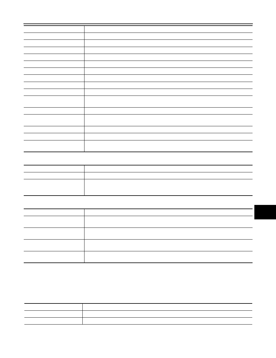
Diagnosis mode

Function Description

DATA MONITOR

The BCM input/output signals are displayed.

ACTIVE TEST

The signals used to activate each device are forcibly supplied from BCM.

SEC-30

< SYSTEM DESCRIPTION >

[WITH INTELLIGENT KEY SYSTEM]

DIAGNOSIS SYSTEM (BCM)

The following table includes information (items) inapplicable to this vehicle. For information (items) applicable
to this vehicle, refer to CONSULT display items.

ACTIVE TEST

Monitor item 

Content

CONFRM ID ALL

Indicates [YET] at all time.
Switch to [DONE] when a registered Intelligent Key is inserted into the key slot.

CONFIRM ID4

CONFIRM ID3

CONFIRM ID2

CONFIRM ID1

TP 4

Indicates the number of ID which has been registered.

TP 3

TP 2

TP 1

PUSH SW

Indicates [ON/OFF] condition of push-button ignition switch.

KEY SW -SLOT

Indicates [ON/OFF] condition of key slot.

Test item

Description

THEFT IND

This test is able to check security indicator lamp operation.
The lamp will be turned on when “ON” on CONSULT screen touched.

U1000 CAN COMM CIRCUIT

SEC-31

< DTC/CIRCUIT DIAGNOSIS >

[WITH INTELLIGENT KEY SYSTEM]

C

D

E

F

G

H

I

J

L

M

A

B

SEC

N

O

P

DTC/CIRCUIT DIAGNOSIS

U1000 CAN COMM CIRCUIT

BCM

BCM : Description

INFOID:0000000009722712

CAN (Controller Area Network) is a serial communication line for real time applications. It is an on-vehicle mul-
tiplex communication line with high data communication speed and excellent error detection ability. Modern
vehicle is equipped with many electronic control unit, and each control unit shares information and links with
other control units during operation (not independent). In CAN communication, control units are connected
with 2 communication lines (CAN H-line, CAN L-line) allowing a high rate of information transmission with less
wiring. Each control unit transmits/receives data but selectively reads required data only.
CAN Communication Signal Chart. Refer to 

LAN-29, "CAN Communication Signal Chart"

.

BCM : DTC Logic

INFOID:0000000009722713

DTC DETECTION LOGIC

BCM : Diagnosis Procedure

INFOID:0000000009722714

1.

PERFORM SELF DIAGNOSTIC

1.

Turn ignition switch ON and wait for 2 seconds or more.

2.

Check “Self Diagnostic Result”.

Is DTC “U1000” displayed?

YES

>> Refer to 

LAN-18, "Trouble Diagnosis Flow Chart"

.

NO

>> Refer to 

GI-44, "Intermittent Incident"

.

IPDM E/R

IPDM E/R : Description

INFOID:0000000009722715

CAN (Controller Area Network) is a serial communication line for real time applications. It is an on-vehicle mul-
tiplex communication line with high data communication speed and excellent error detection ability. Modern
vehicle is equipped with many electronic control unit, and each control unit shares information and links with
other control units during operation (not independent). In CAN communication, control units are connected
with 2 communication lines (CAN-H line, CAN-L line) allowing a high rate of information transmission with less
wiring. Each control unit transmits/receives data but selectively reads required data only.
CAN Communication Signal Chart. Refer to 

LAN-29, "CAN Communication Signal Chart"

.

IPDM E/R : DTC Logic

INFOID:0000000009722716

DTC DETECTION LOGIC

IPDM E/R : Diagnosis Procedure

INFOID:0000000009722717

1.

PERFORM SELF DIAGNOSTIC

DTC

CONSULT display de-

scription

DTC Detection Condition

Possible cause

U1000

CAN COMM

When BCM cannot communicate CAN com-
munication signal continuously for 2 seconds 
or more.

CAN communication system

DTC

CONSULT display de-

scription

DTC Detection Condition

Possible cause

U1000

CAN COMM CIRCUIT

When IPDM E/R cannot communicate CAN 
communication signal continuously for 2 
seconds or more

CAN communication system

SEC-32

< DTC/CIRCUIT DIAGNOSIS >

[WITH INTELLIGENT KEY SYSTEM]

U1000 CAN COMM CIRCUIT

1.

Turn the ignition switch ON and wait for 2 seconds or more.

2.

Check “Self Diagnostic Result” of IPDM E/R.

Is DTC “U1000” displayed?

YES

>> Refer to 

LAN-18, "Trouble Diagnosis Flow Chart"

.

NO

>> Refer to 

GI-44, "Intermittent Incident"

.


содержание   ..  1231  1232  1233  1234   ..