Nissan Murano. Manual - part 1231


  Главная      Nissan     Nissan Murano (2014 year) - Service Manual


поиск по сайту            


содержание   ..  1229  1230  1231  1232   ..


Nissan Murano. Manual - part 1231


VEHICLE SECURITY SYSTEM

SEC-21

< SYSTEM DESCRIPTION >

[WITH INTELLIGENT KEY SYSTEM]

C

D

E

F

G

H

I

J

L

M

A

B

SEC

N

O

P

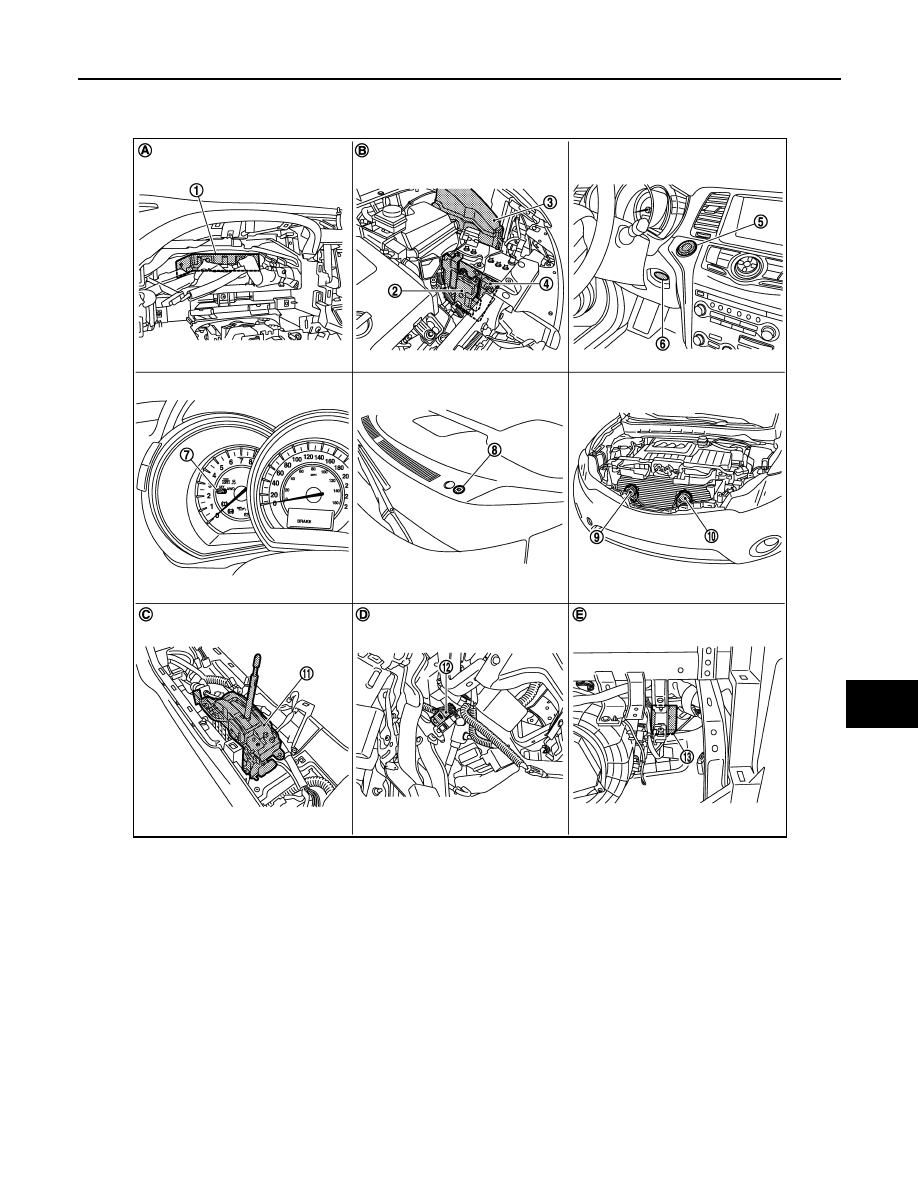
Component Parts Location

INFOID:0000000009722706

1.

BCM

2.

TCM

3.

IPDM E/R

4.

ECM

5.

Push-button ignition switch

6.

Key slot

7.

Combination meter (key warning lamp)

8.

Security indicator lamp

9.

Horn (high)

10. Horn (low)

11.

CVT shift selector (detention switch)

12. Stop lamp switch

13. Remote keyless entry receiver

A.

Behind the combination meter

B.

Engine room (LH)

C.

View with the center console as-
sembly removed

D.

Behind the instrument lower panel LH

E.

Behind the instrument lower panel RH

JMKIA1825ZZ

SEC-22

< SYSTEM DESCRIPTION >

[WITH INTELLIGENT KEY SYSTEM]

VEHICLE SECURITY SYSTEM

Component Description

INFOID:0000000009722707

1.

Front power window switch (passen-
ger side)

2.

Inside key antenna (console)

3.

Inside key antenna (luggage room)

4.

Back door lock assembly (back door 
switch)

5.

Front door switch (driver side)

6.

power window main switch (door 
lock and unlock switch)

A.

Under the rear seat seatback

JMKIA4874ZZ

Component Reference

BCM

SEC-74

Horn relay 1

DLK-133

Horn relay 2

DLK-133

Security indicator lamp

SEC-91

Door switch

DLK-97

Back door lock assembly (back door witch)

DLK-98

Door key cylinder switch

DLK-110

DIAGNOSIS SYSTEM (BCM)

SEC-23

< SYSTEM DESCRIPTION >

[WITH INTELLIGENT KEY SYSTEM]

C

D

E

F

G

H

I

J

L

M

A

B

SEC

N

O

P

DIAGNOSIS SYSTEM (BCM)

COMMON ITEM

COMMON ITEM : CONSULT Function (BCM - COMMON ITEM)

INFOID:0000000010037789

APPLICATION ITEM

CONSULT performs the following functions via CAN communication with BCM.

SYSTEM APPLICATION

BCM can perform the following functions for each system.
NOTE:
It can perform the diagnosis modes except the following for all sub system selection items.

×

: Applicable item

NOTE:

• *1: For models with rain sensor this mode is displayed, but is not used.

• *2: This item is displayed, but is not used. 

FREEZE FRAME DATA (FFD)

Diagnosis mode

Function Description

Work Support

Changes the setting for each system function.

Self Diagnostic Result

Displays the diagnosis results judged by BCM.

CAN Diag Support Monitor

Monitors the reception status of CAN communication viewed from BCM.

Data Monitor

The BCM input/output signals are displayed.

Active Test

The signals used to activate each device are forcibly supplied from BCM.

Ecu Identification

The BCM part number is displayed.

Configuration

• Read and save the vehicle specification.
• Write the vehicle specification when replacing BCM.

System

Sub system selection item

Diagnosis mode

Work Support

Data Monitor

Active Test

Door lock

DOOR LOCK

×

×

×

Rear window defogger

REAR DEFOGGER

×

×

Warning chime

BUZZER

×

×

Interior room lamp timer

INT LAMP

×

×

×

Exterior lamp

HEAD LAMP

×

×

×

Wiper and washer

WIPER

×

*

1

×

×

Turn signal and hazard warning lamps

FLASHER

×

×

×

AIR CONDITONER*

2

• Intelligent Key system
• Engine start system

INTELLIGENT KEY

×

×

×

Combination switch

COMB SW

×

Body control system

BCM

×

NVIS - NATS

IMMU

×

×

Interior room lamp battery saver

BATTERY SAVER

×

×

×

Back door opener system

TRUNK

×

×

Vehicle security system

THEFT ALM

×

×

×

RAP system

RETAINED PWR

×

Signal buffer system

SIGNAL BUFFER

×

×

TPMS

TPMS (AIR PRESSURE MONITOR)

×

×

×

SEC-24

< SYSTEM DESCRIPTION >

[WITH INTELLIGENT KEY SYSTEM]

DIAGNOSIS SYSTEM (BCM)

The BCM records the following vehicle condition at the time a particular DTC is detected, and displays on
CONSULT.

NOTE:

*: Power supply position shifts to “LOCK” from “OFF”, when ignition switch is in the OFF position, selector lever is in the P position, and
any of the following conditions are met.

• Closing door

• Opening door

• Door is locked using door request switch

• Door is locked using Intelligent Key

The power supply position shifts to “ACC” when the push-button ignition switch (push switch) is pushed at “LOCK”.

INTELLIGENT KEY

INTELLIGENT KEY : CONSULT Function (BCM - INTELLIGENT KEY)

INFOID:0000000010037856

BCM CONSULT FUNCTION

CONSULT performs the following functions via CAN communication with BCM.

CONSULT screen item

Indication/Unit

Description

Vehicle Speed

km/h

Vehicle speed of the moment a particular DTC is detected

Odo/Trip Meter

km

Total mileage (Odometer value) of the moment a particular DTC is detected

Vehicle Condition

SLEEP>LOCK

Power position status of 
the moment a particular 
DTC is detected

While turning BCM status from low power consumption mode to 
normal mode (Power supply position is “LOCK”*)

SLEEP>OFF

While turning BCM status from low power consumption mode to 
normal mode (Power supply position is “OFF”.)

LOCK>ACC

While turning power supply position from “LOCK” to “ACC”

ACC>ON

While turning power supply position from “ACC” to “IGN”

RUN>ACC

While turning power supply position from “RUN” to “ACC” (Vehicle 
is stopping and selector lever is except P position.)

CRANK>RUN

While turning power supply position from “CRANKING” to “RUN” 
(From cranking up the engine to run it)

RUN>URGENT

While turning power supply position from “RUN“ to “ACC” (Emer-
gency stop operation)

ACC>OFF

While turning power supply position from “ACC” to “OFF”

OFF>LOCK

While turning power supply position from “OFF” to “LOCK”*

OFF>ACC

While turning power supply position from “OFF” to “ACC”

ON>CRANK

While turning power supply position from “IGN” to “CRANKING”

OFF>SLEEP

While turning BCM status from normal mode (Power supply posi-
tion is “OFF”.) to low power consumption mode

LOCK>SLEEP

While turning BCM status from normal mode (Power supply posi-
tion is “LOCK”*) to low power consumption mode

LOCK

Power supply position is “LOCK”*

OFF

Power supply position is “OFF” (Ignition switch OFF)

ACC

Power supply position is “ACC” (Ignition switch ACC)

ON

Power supply position is “IGN” (Ignition switch ON with engine 
stopped)

ENGINE RUN

Power supply position is “RUN” (Ignition switch ON with engine 
running)

CRANKING

Power supply position is “CRANKING” (At engine cranking)

IGN Counter

0 - 39

The number of times that ignition switch is turned ON after DTC is detected
• The number is 0 when a malfunction is detected now.
• The number increases like 1 

 2 

 3...38 

 39 after returning to the normal condition 

whenever ignition switch OFF 

 ON.

• The number is fixed to 39 until the self-diagnosis results are erased if it is over 39.


содержание   ..  1229  1230  1231  1232   ..