Nissan Murano. Manual - part 119


  Главная      Nissan     Nissan Murano (2014 year) - Service Manual


поиск по сайту            


содержание   ..  117  118  119  120   ..


Nissan Murano. Manual - part 119


AV-254

< DTC/CIRCUIT DIAGNOSIS >

[BOSE AUDIO WITHOUT NAVIGATION]

VERTICAL SYNCHRONIZING (VP) SIGNAL CIRCUIT

VERTICAL SYNCHRONIZING (VP) SIGNAL CIRCUIT

Description

INFOID:0000000009721768

In composite image (AUX and camera image), transmit the vertical synchronizing (VP) signal and horizontal
synchronizing (HP) signal from display unit to AV control unit so as to synchronize the RGB images displayed
with AV control unit such as the image quality adjusting menu, etc.

Diagnosis Procedure

INFOID:0000000009721769

1.

CHECK CONTINUITY VERTICAL SYNCHRONIZING (VP) SIGNAL CIRCUIT

1.

Turn ignition switch OFF.

2.

Disconnect display unit connector and AV control unit connector.

3.

Check continuity between display unit harness connector and AV control unit harness connector.

4.

Check continuity between display unit harness connector and ground.

Is the inspection result normal?

YES

>> GO TO 2.

NO

>> Repair harness or connector.

2.

CHECK VERTICAL SYNCHRONIZING (VP) SIGNAL

1.

Connect display unit connector and AV control unit connector.

2.

Turn ignition switch ON.

3.

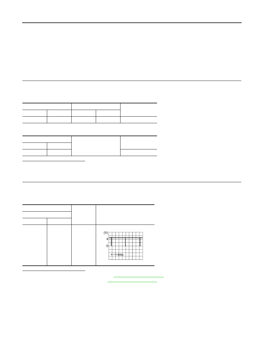
Check signal between display unit harness connector and ground.

Is the inspection result normal?

YES

>> Replace AV control unit. Refer to 

AV-276, "Exploded View"

.

NO

>> Replace display unit. Refer to 

AV-277, "Exploded View"

.

Display unit

AV control unit

Continuity

Connector

Terminal

Connector

Terminal

M194

20

M172

50

Existed

Display unit

Ground

Continuity

Connector

Terminal

M194

20

Not existed

(+)

(

)

Reference value

Display unit

Connector

Terminal

M194

20

Ground

SKIB3598E

AV

COMPOSITE IMAGE SIGNAL CIRCUIT

AV-255

< DTC/CIRCUIT DIAGNOSIS >

[BOSE AUDIO WITHOUT NAVIGATION]

C

D

E

F

G

H

I

J

K

L

M

B

A

O

P

COMPOSITE IMAGE SIGNAL CIRCUIT

Description

INFOID:0000000009721770

AV control unit that inputs the camera image signal and AUX image signal transmits the composite image sig-
nal to the display unit.

Diagnosis Procedure

INFOID:0000000009721771

1.

CHECK CONTINUITY COMPOSITE IMAGE SIGNAL CIRCUIT

1.

Turn ignition switch OFF.

2.

Disconnect AV control unit connector and display unit connector.

3.

Check continuity between AV control unit harness connector and display unit harness connector.

4.

Check continuity between AV control unit harness connector and ground.

Is the inspection result normal?

YES

>> GO TO 2.

NO

>> Repair harness or connector.

2.

CHECK COMPOSITE IMAGE SIGNAL

1.

Connect AV control unit connector and display unit connector.

2.

Turn ignition switch ON.

3.

Check signal between AV control unit harness connector and ground.

Is the inspection result normal?

YES

>> Replace display unit. Refer to 

AV-277, "Exploded View"

.

NO

>> Replace AV control unit. Refer to 

AV-276, "Exploded View"

.

AV control unit

Display unit

Continuity

Connector

Terminal

Connector

Terminal

M172

47

M194

15

Existed

AV control unit

Ground

Continuity

Connector

Terminal

M172

47

Not existed

(+)

(

)

Condition

Reference value

AV control unit

Connector

Terminal

M172

47

Ground

At camera image is dis-
played.

SKIB2251J

AV-256

< DTC/CIRCUIT DIAGNOSIS >

[BOSE AUDIO WITHOUT NAVIGATION]

AUX IMAGE SIGNAL CIRCUIT

AUX IMAGE SIGNAL CIRCUIT

Description

INFOID:0000000009721772

• Transmits the image signal of AUX device from auxiliary input jacks to AV control unit.
• AV control unit transmits the image signal that is input to the display unit.

Diagnosis Procedure

INFOID:0000000009721773

1.

CHECK CONTINUITY AUX IMAGE SIGNAL CIRCUIT

1.

Turn ignition switch OFF.

2.

Disconnect auxiliary input jacks connector and AV control unit connector.

3.

Check continuity between auxiliary input jacks harness connector and AV control unit harness connector.

4.

Check continuity between auxiliary input jacks harness connector and ground.

Is the inspection result normal?

YES

>> GO TO 2.

NO

>> Repair harness or connector.

2.

CHECK AUX IMAGE SIGNAL

1.

Connect auxiliary input jacks connector and AV control unit connector.

2.

Turn ignition switch ON.

3.

Check signal between auxiliary input jacks harness connector and ground.

Is the inspection result normal?

YES

>> Replace AV control unit. Refer to 

AV-276, "Exploded View"

.

NO

>> Check that there is no malfunction in the external device.

Auxiliary input jacks

AV control unit

Continuity

Connector

Terminal

Connector

Terminal

M253

7

M173

61

Existed

Auxiliary input jacks

Ground

Continuity

Connector

Terminal

M253

7

Not existed

(+)

(

)

Condition

Reference value

Auxiliary input jacks

Connector

Terminal

M253

7

Ground

At AUX image is displayed.

SKIB2251J

AV

CAMERA IMAGE SIGNAL CIRCUIT

AV-257

< DTC/CIRCUIT DIAGNOSIS >

[BOSE AUDIO WITHOUT NAVIGATION]

C

D

E

F

G

H

I

J

K

L

M

B

A

O

P

CAMERA IMAGE SIGNAL CIRCUIT

Description

INFOID:0000000009721774

• AV control unit outputs camera power supply to rear view camera and inputs camera image signal from rear

view camera when the reverse signal is input.

• AV control unit transmits the camera image signal to the display unit.

Diagnosis Procedure

INFOID:0000000009721775

1.

CHECK CONTINUITY CAMERA POWER SUPPLY CIRCUIT

1.

Turn ignition switch OFF.

2.

Disconnect AV control unit connector and rear view camera connector.

3.

Check continuity between AV control unit harness connector and rear view camera harness connector.

4.

Check continuity between AV control unit harness connector and ground.

Is inspection result normal?

YES

>> GO TO 2.

NO

>> Repair harness or connector.

2.

CHECK VOLTAGE CAMERA POWER SUPPLY

1.

Connect AV control unit connector and rear view camera connector.

2.

Turn ignition switch ON.

3.

Shift the selector lever to “R”.

4.

Check voltage between AV control unit harness connector and ground.

Is inspection result normal?

YES

>> GO TO 3.

NO

>> Replace AV control unit. Refer to 

AV-276, "Exploded View"

.

3.

CHECK CONTINUITY CAMERA IMAGE SIGNAL CIRCUIT

1.

Turn ignition switch OFF.

2.

Disconnect AV control unit connector and rear view camera connector.

3.

Check continuity between AV control unit harness connector and rear view camera harness connector.

4.

Check continuity between AV control unit harness connector and ground.

AV control unit

Rear view camera

Continuity

Connector

Terminal

Connector

Terminal

M173

73

D192

1

Existed

AV control unit

Ground

Continuity

Connector

Terminal

M173

73

Not existed

(+)

(

)

Condition

Voltage

(Approx.)

AV control unit

Connector

Terminal

M173

73

Ground

Selector lever is in “R”.

6.0 V

AV control unit

Rear view camera

Continuity

Connector

Terminal

Connector

Terminal

M173

62

D192

3

Existed


содержание   ..  117  118  119  120   ..