содержание .. 1187 1188 1189 1190 ..
Nissan Murano. Manual - part 1189
REAR STABILIZER
RSU-15
< REMOVAL AND INSTALLATION >
C
D
F
G
H
I
J
K
L
M
A
B
RSU
N
O
P
REAR STABILIZER
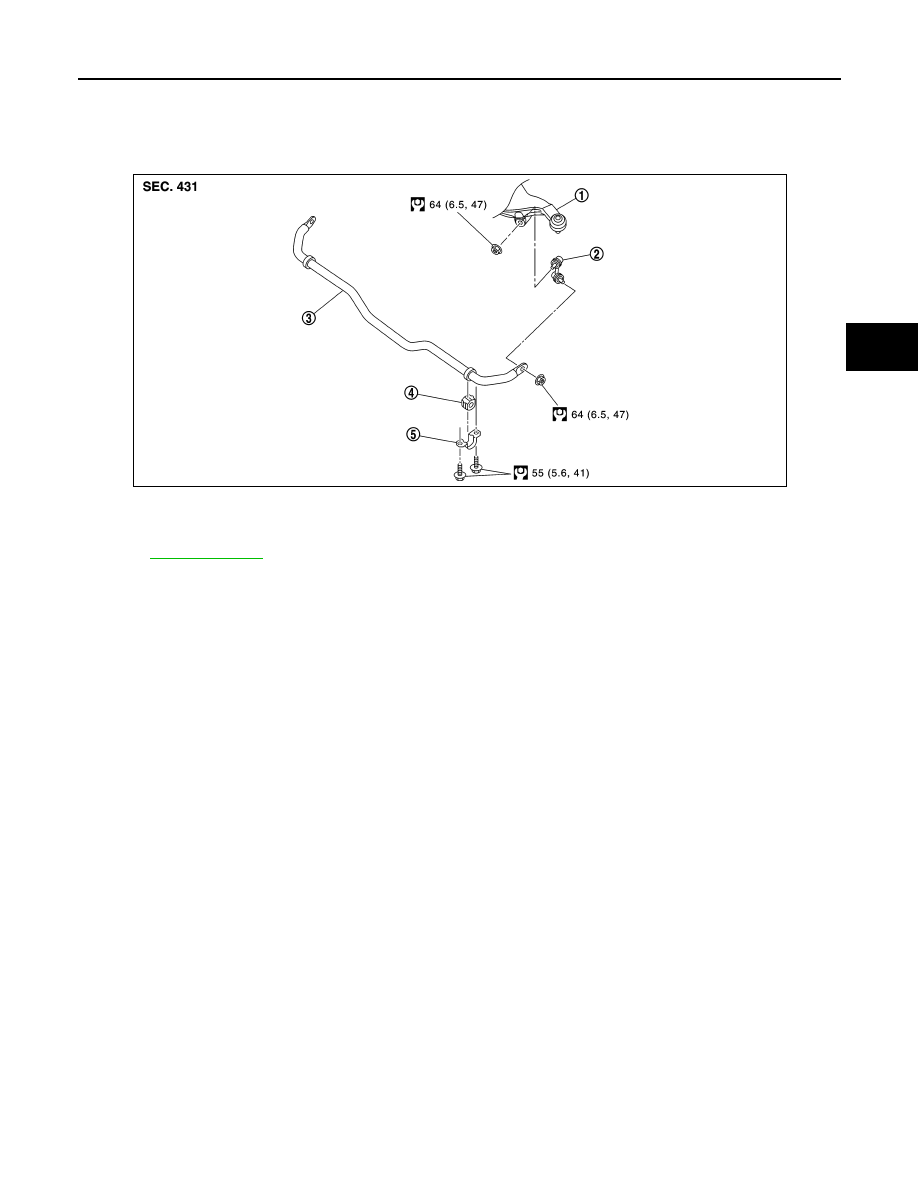
Exploded View
INFOID:0000000009721440
Removal and Installation
INFOID:0000000009721441
REMOVAL
1.
Remove tires with power tool.
2.
Remove stabilizer connecting rod.
CAUTION:
Apply a matching mark to identify the installation position.
3.
Remove mounting bolts on stabilizer clamp and remove stabilizer bar with power tool.
INSTALLATION
Note the following, and install in the reverse order of removal.
• Check the matching mark when installing.
• Tighten the mounting nut to the specified torque while holding a hexagonal part of stabilizer connecting rod
side.
Inspection
INFOID:0000000009721442
INSPECTION AFTER REMOVAL
Check stabilizer bar, stabilizer bushing, stabilizer clamp, stabilizer connecting rod, for any deformation, crack
or damage. Replace if necessary.
1.
Suspension arm
2.
Stabilizer connecting rod
3.
Stabilizer bar
4.
Stabilizer bushing
5.
Stabilizer clamp
for symbols in the figure.
JPEIB0268GB