содержание .. 1152 1153 1154 1155 ..
Nissan Murano. Manual - part 1154
RAX-24
< SERVICE DATA AND SPECIFICATIONS (SDS)
[AWD]
SERVICE DATA AND SPECIFICATIONS (SDS)
SERVICE DATA AND SPECIFICATIONS (SDS)
SERVICE DATA AND SPECIFICATIONS (SDS)
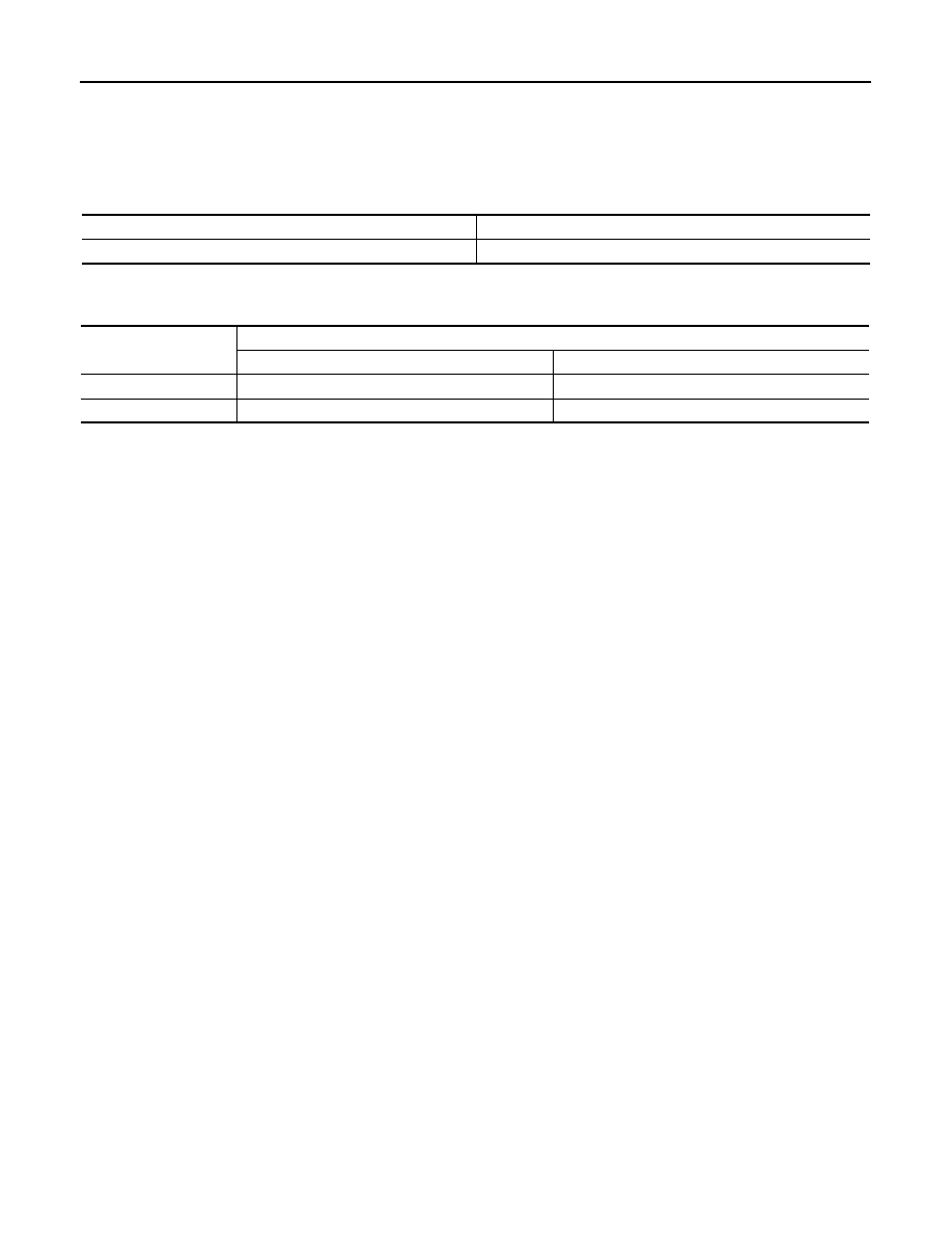
Wheel Bearing
INFOID:0000000009720617
Drive Shaft
INFOID:0000000009720618
Item
Standard
Axial end play
0.05 mm (0.002 in) or less
Item
Standard
Wheel side
Final drive side
Grease quantity
35 – 45 g (1.24 – 1.58 oz)
45 – 50 g (1.59 – 1.76 oz)
Boots installed length
91.2 mm (3.591 in)
126.9 mm (5.00 in)