Nissan Murano. Manual - part 1151


  Главная      Nissan     Nissan Murano (2014 year) - Service Manual


поиск по сайту            


содержание   ..  1149  1150  1151  1152   ..


Nissan Murano. Manual - part 1151


RAX-12

< PREPARATION >

[AWD]

PREPARATION

PREPARATION

PREPARATION

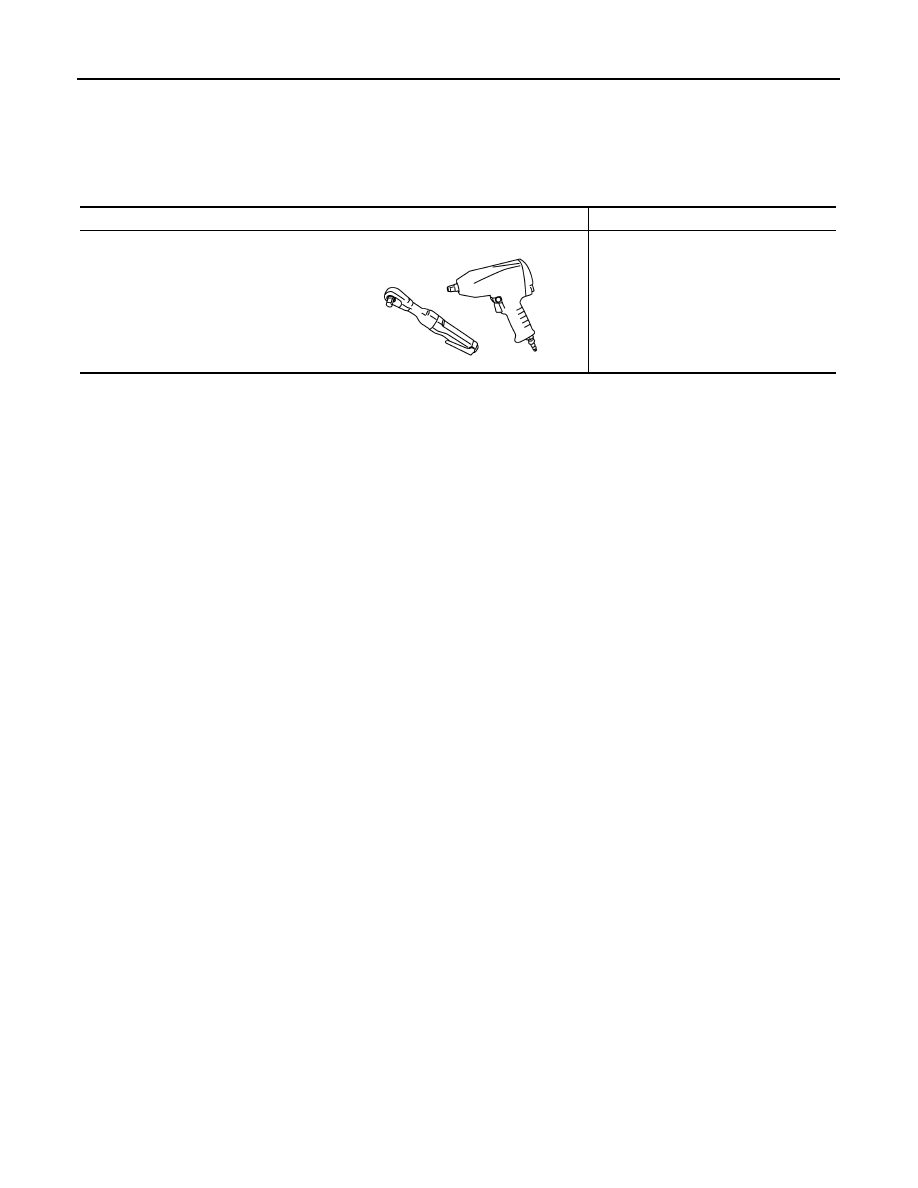
Commercial Service Tool

INFOID:0000000009720606

Tool name

Description

Power tool

Loosening bolts and nuts

PBIC0190E

REAR WHEEL HUB AND HOUSING

RAX-13

< PERIODIC MAINTENANCE >

[AWD]

C

E

F

G

H

I

J

K

L

M

A

B

RAX

N

O

P

PERIODIC MAINTENANCE

REAR WHEEL HUB AND HOUSING

Inspection

INFOID:0000000009720607

MOUNTING INSPECTION

Make sure the mounting conditions (looseness, back lash) of each component and component conditions
(wear, damage) are normal.

WHEEL BEARING INSPECTION

• Move wheel hub and bearing assembly in the axial direction by hand. Make sure there is no looseness of

wheel bearing. 

• Rotate wheel hub and bearing assembly and make sure there is no unusual noise or other irregular condi-

tions. If there is any of irregular conditions, replace wheel hub and bearing assembly.

Standard

Axial end play

: Refer to 

RAX-24, "Wheel Bearing"

.

RAX-14

< PERIODIC MAINTENANCE >

[AWD]

REAR DRIVE SHAFT

REAR DRIVE SHAFT

Inspection

INFOID:0000000009720608

• Check drive shaft mounting point and joint for looseness and other damage.
• Check boot for cracks and other damage.

CAUTION:

Replace entire drive shaft assembly when noise or vibration occurs from drive shaft.

REAR WHEEL HUB AND HOUSING

RAX-15

< REMOVAL AND INSTALLATION >

[AWD]

C

E

F

G

H

I

J

K

L

M

A

B

RAX

N

O

P

REMOVAL AND INSTALLATION

REAR WHEEL HUB AND HOUSING

Exploded View

INFOID:0000000009720609

Removal and Installation

INFOID:0000000009720610

REMOVAL

1.

Remove tires with power tool.

2.

Remove wheel sensor and sensor harness. Refer to 

BRC-124, "REAR WHEEL SENSOR : Exploded

View"

.

3.

Remove caliper assembly. Hang caliper assembly not to interfere with work. Refer to 

BR-48, "BRAKE

CALIPER ASSEMBLY : Exploded View"

.

CAUTION:

Never depress brake pedal while caliper assembly is removed.

4.

Remove disc rotor. Refer to 

BR-49, "BRAKE CALIPER ASSEMBLY : Removal and Installation"

.

5.

Remove cotter pin, then loosen suspension arm mounting nut of axle housing. Refer to 

RSU-16,

"Exploded View"

.

6.

Remove cotter pin, and then loosen wheel hub lock nut with power tool.

7.

Patch wheel hub lock nut with a piece of wood. Hammer the wood to disengage wheel hub and bearing
assembly from drive shaft. Remove the wheel hub lock nut.

CAUTION:

• Never place drive shaft joint at an extreme angle. Also be careful not to overextend slide joint.
• Never allow drive shaft to hang down without support for housing (or joint sub-assembly), shaft

and the other parts.

NOTE:
Use suitable puller, if wheel hub and bearing assembly and drive shaft cannot be separated even after
performing the above procedure.

8.

Remove wheel hub and bearing assembly.

9.

Remove parking brake shoe and parking brake cable from back plate. Refer to 

PB-8, "Exploded View"

and 

PB-6, "Exploded View"

.

1.

Ball seat

2.

Bushing

3.

Cotter pin

4.

Axle housing

5.

Hub cap

6.

Back plate

7.

Anchor block

8.

Wheel hub and bearing assembly

9.

Wheel hub lock nut

Refer to 

GI-4, "Components"

 for symbols in the figure.

JSDIA3328GB


содержание   ..  1149  1150  1151  1152   ..