Nissan Murano. Manual - part 68


  Главная      Nissan     Nissan Murano (2014 year) - Service Manual


поиск по сайту            


содержание   ..  66  67  68  69   ..


Nissan Murano. Manual - part 68


AV-50

< SYSTEM DESCRIPTION >

[BASE AUDIO WITH COLOR DISPLAY]

COMPONENT PARTS

SYSTEM DESCRIPTION

COMPONENT PARTS

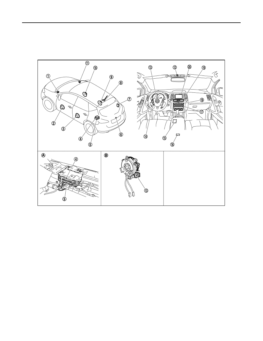
Component Parts Location

INFOID:0000000009721597

Component Description

INFOID:0000000009721598

1.

Front squawker LH

2.

Front door speaker LH

3.

Rear door speaker LH

4.

Satellite radio tuner

5.

TEL adapter unit

6.

Rear view camera

7.

TEL antenna

8.

Antenna base (antenna amp. and 
satellite radio antenna)

9.

Rear door speaker RH

10.

Front door speaker RH

11. Front squawker RH

12. Microphone

13.

Steering angle sensor

14. Steering switch

15. USB connector

16.

Auxiliary input jacks

17. Preset switch

18. AV control unit

19.

Multifunction switch

20. Display unit

A.

Luggage floor finisher is removed 
condition

B.

Spiral cable part

JSNIA3508ZZ

AV

COMPONENT PARTS

AV-51

< SYSTEM DESCRIPTION >

[BASE AUDIO WITH COLOR DISPLAY]

C

D

E

F

G

H

I

J

K

L

M

B

A

O

P

Part name

Description

AV control unit

• It is the master unit of the MULTI AV system, and it is connected to each control 

unit by communication. It operates each system according to communication sig-
nals from the AV control unit.

• The AV control unit includes the audio, rear view monitor, USB connection and ve-

hicle information functions.

• It is connected to ECM and combination meter via CAN communication to obtain 

necessary information for the vehicle information function.

• It is connected to BCM via CAN communication transmitting/receiving for the ve-

hicle settings function.

• It inputs the illumination signals that are required for the display dimming control.
• It inputs the signals for driving status recognition (vehicle speed, reverse and park-

ing brake). 

• It supplies power to the rear camera.
• Sound signal is transmitted to each speaker.
• TEL voice signal is input from TEL adapter unit.

Display unit

• Display image is controlled by the serial communication from AV control unit.
• It receives the power (signal VCC and inverter VCC) from the AV control unit and 

operates.

• RGB image signal is input from AV control unit (RGB, RGB area and RGB synchro-

nizing).

• Composite image signals (auxiliary input and camera images) are input from AV 

control unit.

• Synchronizing signal (HP, VP) is output to AV control unit.

Front door speaker

• Outputs sound signal from AV control unit.
• Outputs sound (high, mid and low range).

Rear door speaker

• Outputs sound signal from AV control unit.
• Outputs sound (high, mid and low range).

Front squawker

• Outputs sound signal from AV control unit.
• Outputs sound (high and mid range).

Multifunction switch

• Operation panel is equipped with the centralized switch where audio and auxiliary 

input, etc. operations are integrated.

• Connected with preset switch via harness, and operation signal is transmitted to 

AV control unit via AV communication. 

Preset switch

• Operation panel is equipped with the centralized switch where audio and air con-

ditioner, etc. operations are integrated.

• Connected with multifunction switch via harness, and operation signal is transmit-

ted to AV control unit via AV communication.

• The disk ejection operating signal is performed by hardwire.

Rear view camera

• Camera power supply is input from AV control unit.
• The image of vehicle rear view is transmitted to AV control unit.

Steering angle sensor

It is connected to the AV control unit and transmits the steering angle sensor signal 
via CAN communication.

Steering switch

• Operations for audio and hands-free phone are possible.
• Steering switch signal (operation signal) is output to AV control unit.

Microphone

• Used for hands-free phone operation.
• Microphone signal is transmitted to TEL adapter unit.
• Power (Microphone VCC) is supplied from TEL adapter unit.

Auxiliary input jacks

Image signal and sound signal of auxiliary input are transmitted to AV control unit.

Antenna base

A radio antenna base integrated with radio antenna amp. and satellite radio antenna 
is adopted.

ANTENNA AMP.

• Radio signal received by rod antenna is amplified and transmitted to AV control 

unit.

• Power (antenna amp. ON signal) is supplied from AV control unit.

SATELLITE RADIO ANTENNA

• Receives satellite radio waves and outputs it to satellite radio tuner.

AV-52

< SYSTEM DESCRIPTION >

[BASE AUDIO WITH COLOR DISPLAY]

COMPONENT PARTS

Satellite radio tuner

• Inputs the satellite radio signal from satellite radio antenna and outputs the sound 

signal to the AV control unit.

• It is controlled with the AV control unit and serial communication (communication 

signal and request signal).

TEL adapter unit

• Inputs the TEL voice signal from TEL antenna and outputs it to the AV control unit.
• It is connected with the AV control unit via AV communication and controlled with 

the AV control unit.

TEL antenna

Receives the TEL voice signal and outputs it to the TEL adapter unit.

USB connector 

Sound signal of USB input is transmitted to AV control unit.

Part name

Description

AV

SYSTEM

AV-53

< SYSTEM DESCRIPTION >

[BASE AUDIO WITH COLOR DISPLAY]

C

D

E

F

G

H

I

J

K

L

M

B

A

O

P

SYSTEM

MULTI AV SYSTEM

MULTI AV SYSTEM : System Diagram

INFOID:0000000009721599

*1: With hands-free phone system
NOTE:
• FLASH AUDIO is not used.
• The name MULTIFUNCTION SWITCH indicates the integration of PRESET SWITCH and MULTIFUNCTION

SWITCH virtually.

• An antenna base integrated with radio antenna amp. and satellite

radio antenna is adopted. 

MULTI AV SYSTEM : System Description

INFOID:0000000009721600

Multi AV system means that the following systems are integrated.

JSNIA5367GB

JSNIA1062GB

FUNCTION NAME

Audio function

Hands-free phone function

Auxiliary input function


содержание   ..  66  67  68  69   ..