содержание .. 932 933 934 935 ..
Nissan X-Trail 32. Manual - part 934
SYSTEM
EC-865
< SYSTEM DESCRIPTION >
[R9M]
C
D
E
F
G
H
I
J
K
L
M
A
EC
N
P
O
INFORMATION DISPLAY (COMBINATION METER) : Engine Oil Pressure Warning
INFOID:0000000011009992
DESIGN/PURPOSE
When engine oil pressure is low, the engine oil pressure warning lamp informs the driver of low oil pressure to
prevent damage to the engine.
Stop/Start warning indicator
Indicates the message when a malfunction is de-
tected in stop/start system.
For detail of Stop/Start warning indicator function,
refer to
EC-848, "STOP/START SYSTEM : System
(M/T models),
"STOP/START SYSTEM : System Description
(CVT models)"
Massage: System fault
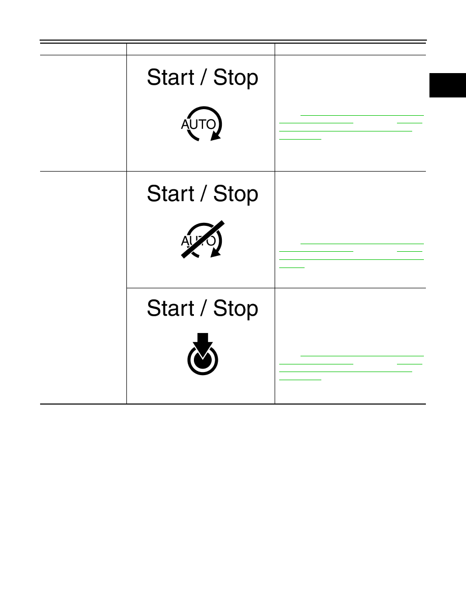
Stop/Start guidance indica-
tor
Indicates the message when the driver performs a
dangerous operation shown below:
• Driver
′
s seat belt is unbuckled and driver
′
s door
is opened. (M/T models)
• Hood is opened.
For detail of Stop/Start guidance indicator function,
refer to
EC-848, "STOP/START SYSTEM : System
(M/T models),
"STOP/START SYSTEM : System Description (M/T
models)"
(CVT models).
Massage: Not available
Indicates the message when the driver performs a
dangerous operation as shown above during stop/
start system operation and the above “Not avail-
able” indication continues for 5 seconds.
For detail of Stop/Start guidance indicator function,
refer to
EC-848, "STOP/START SYSTEM : System
(M/T models),
"STOP/START SYSTEM : System Description
(CVT models)"
Massage: Push engine start button
Item
Symbol
Function
JSBIA4032GB
JSBIA4030GB
JSBIA4031GB