Nissan X-Trail 32. Manual - part 742


  Главная      Nissan     Nissan X-Trail 32 - Service Manual


поиск по сайту            


содержание   ..  740  741  742  743   ..


Nissan X-Trail 32. Manual - part 742


ECM

EC-97

< ECU DIAGNOSIS INFORMATION >

[MR20DD]

C

D

E

F

G

H

I

J

K

L

M

A

EC

N

P

O

45

(G)

128

(B)

LIN communication line

Input/

Output

[Ignition switch: ON]

12 V 

46

(LG)

42

(B)

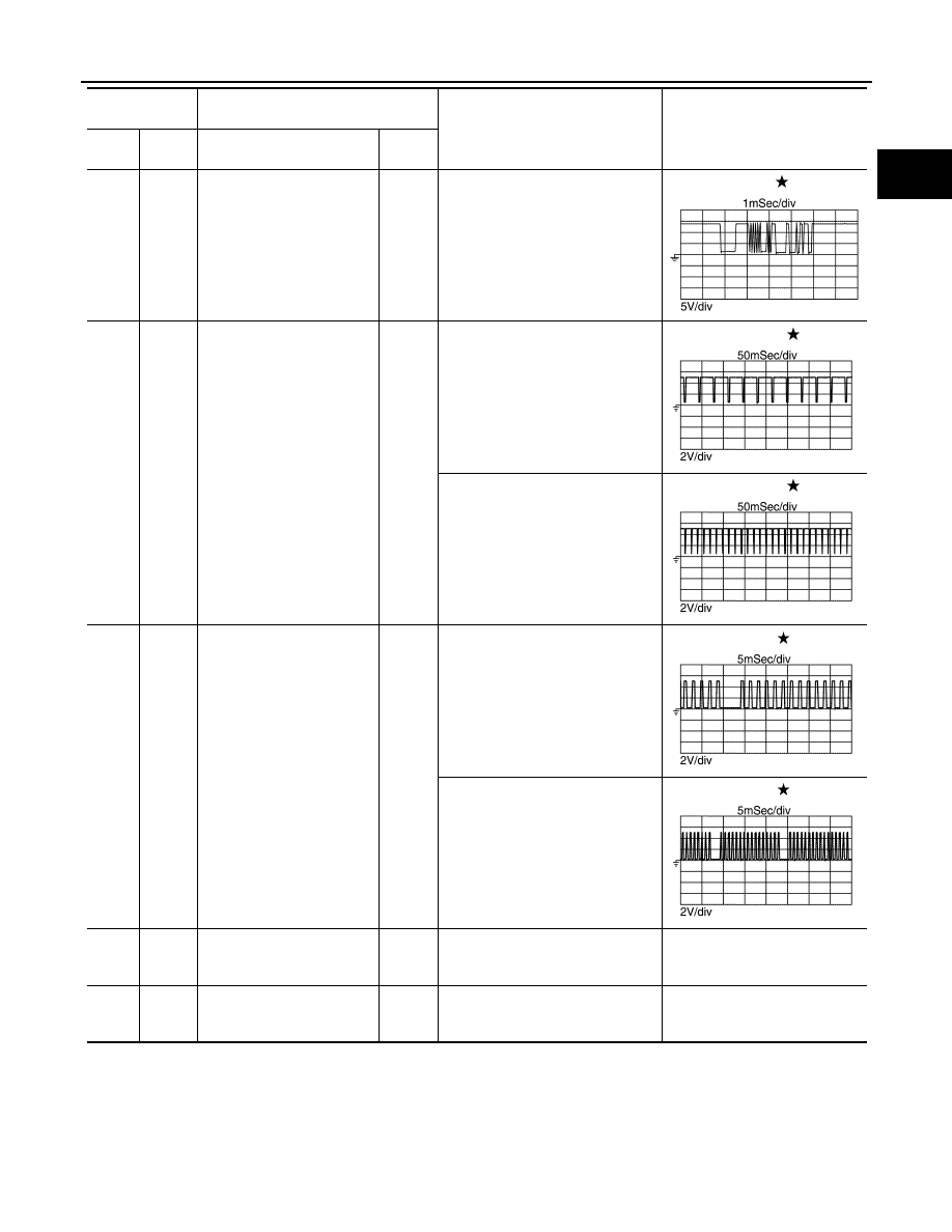
Exhaust valve timing control 
position sensor

Input

[Engine is running]
• Engine: after warming up
• Idle speed

NOTE:
The pulse cycle changes depend-
ing on rpm at idle.

1.0 – 2.0 

[Engine is running]
• Engine: after warming up
• Engine speed: 2,000 rpm

1.0 – 2.0 

48

(GR)

44

(BR)

Crankshaft position sensor

Input

[Engine is running]
• Engine: after warming up
• Idle speed

NOTE:
The pulse cycle changes depend-
ing on rpm at idle.

4.0 V 

[Engine is running]
• Engine: after warming up
• Engine speed: 2,000 rpm

4.0 V 

49

(Y)

55

(GR)

Fuel injector driver power 
supply 1

Input

[Engine is running]
• Engine: after warming up
• Idle speed

BATTERY VOLTAGE

(11 – 14 V) 

50

(V)

54

(BR)

High pressure fuel pump re-
lay

Input

[Engine is running]
• Engine: after warming up
• Idle speed

BATTERY VOLTAGE

(11 – 14 V) 

Terminal No.

(Wire color)

Description

Condition

Value

(Approx.)

+

Signal name

Input/

Output

JPBIA4273ZZ

JPBIA4730ZZ

JPBIA4731ZZ

JPBIA4728ZZ

JPBIA4729ZZ

EC-98

< ECU DIAGNOSIS INFORMATION >

[MR20DD]

ECM

51

(W)

54

(BR)

High pressure fuel pump(HI)

Output

[Engine is running]
• Engine: after warming up
• Idle speed

NOTE:
The pulse cycle changes depend-
ing on rpm at idle.

BATTERY VOLTAGE

(11 – 14 V) 

[Engine is running]
• Engine: after warming up
• Engine speed: 2,000 rpm

BATTERY VOLTAGE

(11 – 14 V) 

52

(B)

128

(B)

High pressure fuel pump(LO)

Output

[Engine is running]
• Engine: after warming up
• Idle speed

NOTE:
The pulse cycle changes depend-
ing on rpm at idle.

BATTERY VOLTAGE

(11 – 14 V) 

[Engine is running]
• Engine: after warming up
• Engine speed: 2,000 rpm

BATTERY VOLTAGE

(11 – 14 V) 

53

(W)

55

(GR)

Fuel injector driver power 
supply 2

Input

[Engine is running]
• Engine: after warming up
• Idle speed

BATTERY VOLTAGE

(11 – 14 V) 

54

(BR)

ECM ground (High pressure 
fuel pump)

55

(GR)

ECM ground (Fuel injector)

56

(B)

ECM ground (Fuel injector)

57

(Y)

59

(B)

Heated oxygen sensor 2

Input

[Engine is running]
• Revving engine from idle to 3,000 

rpm quickly after the following 
conditions are met

- Engine: after warming up
- Keeping the engine speed be-

tween 3,500 and 4,000 rpm for 1 
minute and at idle for 1 minute un-
der no load

0 – 1.0 V

Terminal No.

(Wire color)

Description

Condition

Value

(Approx.)

+

Signal name

Input/

Output

JPBIA4722ZZ

JPBIA4723ZZ

JPBIA4724ZZ

JPBIA4725ZZ

ECM

EC-99

< ECU DIAGNOSIS INFORMATION >

[MR20DD]

C

D

E

F

G

H

I

J

K

L

M

A

EC

N

P

O

59

(B)

Sensor ground (Heated oxy-
gen sensor 2)

60

(R)

75

(B)

Sensor power supply (Throt-
tle position sensor 1, throttle 
position sensor 2)

[Ignition switch: ON]

5 V

62

(B)

Shield

63

(G)

75

(B)

Throttle position sensor 1

Input

[Ignition switch: ON]
• Engine stopped
• Selector lever: D position
• Accelerator pedal: Fully released

More than 0.36 V

[Ignition switch: ON]
• Engine stopped
• Selector lever: D position
• Accelerator pedal: Fully de-

pressed

Less than 4.75 V

64

(Y)

128

(B)

Air fuel ratio (A/F) sensor 1

Input

[Engine is running]
• Engine: after warming up
• Engine speed: 2,000 rpm

2.2 V

Varies with air fuel ratio.

65

(W)

128

(B)

Throttle control motor power 
supply

Input

[Ignition switch: ON]

BATTERY VOLTAGE

(11 - 14 V)

69

(R)

128

(B)

Throttle control motor 
(OPEN)

Output

[Ignition switch: ON]
• Engine: Stopped
• Selector lever: D position
• Accelerator pedal: Fully de-

pressed

3.2 V 

70

(—)

Shield

71

(W)

75

(B)

Throttle position sensor 2

Input

[Ignition switch: ON]
• Engine stopped
• Selector lever: D position
• Accelerator pedal: Fully released

Less than 4.75 V

[Ignition switch: ON]
• Engine stopped
• Selector lever: D position
• Accelerator pedal: Fully de-

pressed

More than 0.36 V

72

(G)

128

(B)

Air fuel ratio (A/F) sensor 1

Input

[Ignition switch: ON]

1.8 V

73

(L)

128

(B)

Throttle control motor 
(CLOSE)

Output

[Ignition switch: ON]
• Engine stopped
• Selector lever: D position
• Accelerator pedal: Fully released

1.8 V 

75

(B)

Sensor ground (Throttle po-
sition sensor 1, throttle posi-
tion sensor 2)

Terminal No.

(Wire color)

Description

Condition

Value

(Approx.)

+

Signal name

Input/

Output

JMBIA0324GB

JMBIA0326GB

EC-100

< ECU DIAGNOSIS INFORMATION >

[MR20DD]

ECM

77

(BG)

128

(B)

EVAP canister purge volume 
control solenoid valve

Output

[Engine is running]
• Idle speed
• Accelerator pedal: Fully released 

after starting engine

BATTERY VOLTAGE

(11 – 14 V) 

[Engine is running]
• Engine speed: 2,000 rpm (Pass-

ing 100 seconds after starting en-
gine)

10 V 

78

(Y)

128

(B)

Ignition signal No.1
Ignition signal No.2
Ignition signal No.3
Ignition signal No.4

Output

[Engine is running]
• Engine: after warming up
• Idle speed

NOTE:
The pulse cycle changes depend-
ing on rpm at idle.

0 – 0.3 V 

82

(BR)

86

(W)

[Engine is running]
• Engine: after warming up
• Engine speed: 2,000 rpm

0.2 – 0.5 V 

90

(SB)

79

(V)

128

(B)

Intake manifold runner con-
trol valve power supply

Input

[Engine is running]
• Engine: after warming up
• Idle speed

BATTERY VOLTAGE

(11 – 14 V) 

80

(V)

128

(B)

Throttle control motor relay

Output

[Ignition switch: OFF]

BATTERY VOLTAGE

(11 – 14 V) 

[Ignition switch: ON]

0 – 1.0 V

81

(G)

128

(B)

Intake manifold runner con-
trol valve (CLOSE)

Output

[Engine is running]
• Engine: after warming up
• Idle speed

0 V

[Engine is running]
• Engine: after warming up
• No load
• When the engine speed is de-

creased from 3,000 rpm to idle 
speed (Accelerator pedal is re-
leased)

Generates a voltage for a mo-

ment

(11 – 14 V) 

Terminal No.

(Wire color)

Description

Condition

Value

(Approx.)

+

Signal name

Input/

Output

JMBIA0327GB

JMBIA0328GB

JPBIA4733ZZ

JPBIA4734ZZ


содержание   ..  740  741  742  743   ..