Nissan X-Trail 32. Manual - part 741


  Главная      Nissan     Nissan X-Trail 32 - Service Manual


поиск по сайту            


содержание   ..  739  740  741  742   ..


Nissan X-Trail 32. Manual - part 741


ECM

EC-93

< ECU DIAGNOSIS INFORMATION >

[MR20DD]

C

D

E

F

G

H

I

J

K

L

M

A

EC

N

P

O

*1: Accelerator pedal position sensor 2 signal and throttle position sensor 2 signal are converted by ECM internally. Thus, they differfrom
ECM terminals voltage signal.

*2: Indicates the intake manifold runner control valve.

*3: Before measuring the terminal voltage, confirm that the battery is fully charged. Refer to 

PG-124, "EXCEPT FOR R9M : Work Proce-

dure"

.

*4: Varies with the atmospheric pressure changed by whether or elevation as this is an absolute pressure sensor.
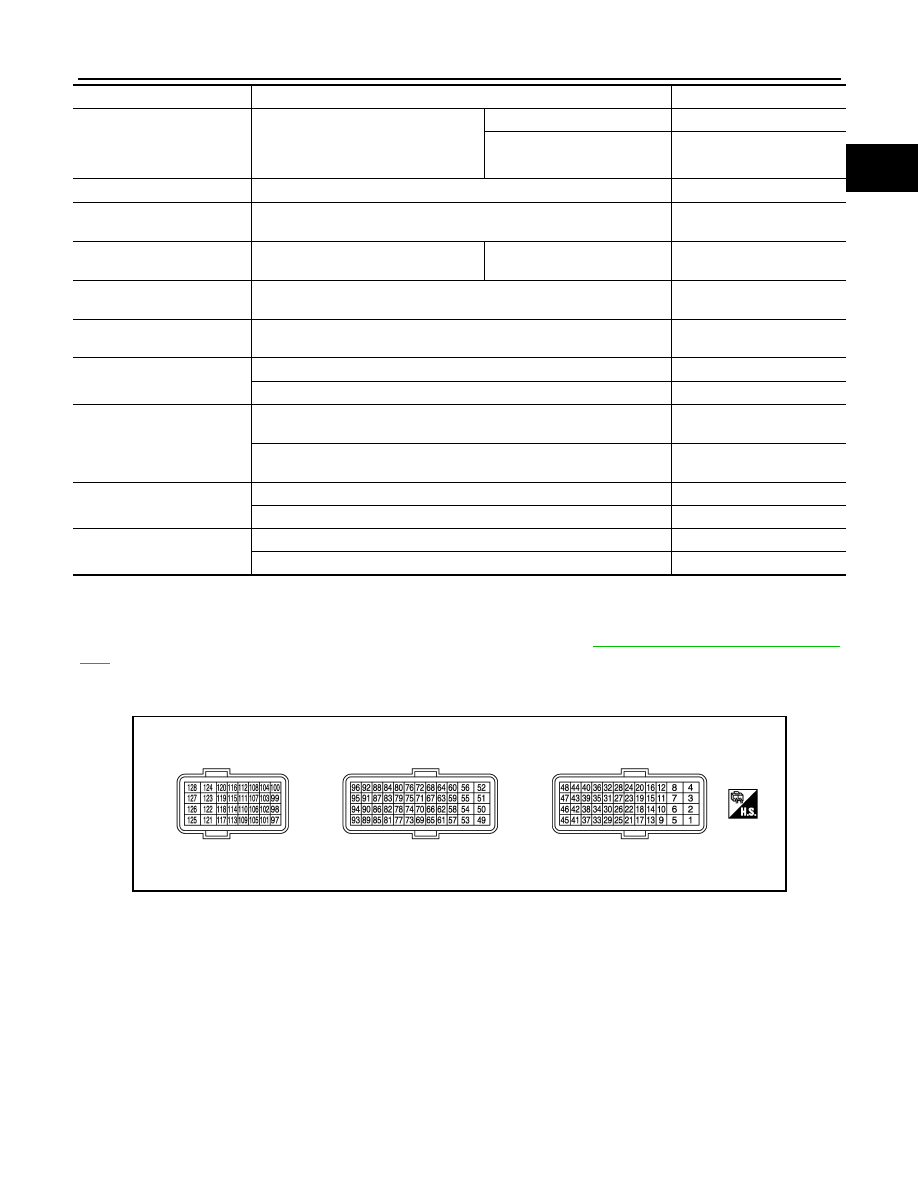
TERMINAL LAYOUT

PHYSICAL VALUES

NOTE:
• ECM is located in the engine room left side near battery.
• Specification data are reference values and are measured between each terminal and ground.
• Pulse signal is measured by CONSULT.

FUEL INJ TIM

• Engine oil temperature: 80

°

C

• Selector lever: P or N position
• A/C switch: OFF
• No  load

Idle

 Approx. 62 deg

2,000 rpm

Approx. 62 deg

FAN DUTY

• Engine: Running

0 - 100%

THRTL STK CNT B1

NOTE:
This item is displayed but are not applicable to this model.

A/F SEN1 (B1)

• Engine: After warming up

Maintaining engine speed at 
2,000 rpm

Fluctuates around 2.2 V

A/F-S ATMSPHRC CRCT B1

Engine: After warming up, idle the engine

Varies depending on vehicle 

environment.

A/F-S ATMSPHRC CRCT UP 
B1

Engine: Running

Varies depending on the 

number of updates.

A/F SEN1 DIAG2 (B1)

DTC P014C and P014D self-diagnosis incomplete.

INCMP

DTC P014C and P014D self-diagnosis is complete.

CMPLT

A/F SEN1 DIAG3 (B1)

The vehicle condition is not within the diagnosis range of DTC P014C or 
P014D.

ABSNT

The vehicle condition is within the diagnosis range of DTC P014C or 
P014D.

PRSNT

HO2 S2 DIAG1 (B1)

DTC P0139 self-diagnosis (delayed response) is incomplete.

INCMP

DTC P0139 self-diagnosis (delayed response) is complete.

CMPLT

HO2 S2 DIAG2 (B1)

DTC P0139 self-diagnosis (slow response) is incomplete.

INCMP

DTC P0139 self-diagnosis (slow response) is complete.

CMPLT

Monitor Item

Condition

Values/Status

JSBIA0505ZZ

EC-94

< ECU DIAGNOSIS INFORMATION >

[MR20DD]

ECM

Terminal No.

(Wire color)

Description

Condition

Value

(Approx.)

+

Signal name

Input/

Output

1

(W)

55

(GR)

Fuel injector No. 1 (HI)
Fuel injector No. 2 (HI)
Fuel injector No. 3 (HI)
Fuel injector No. 4 (HI)

Output

[Engine is running]
• Engine: after warming up
• Idle speed

NOTE:
The pulse cycle changes depend-
ing on rpm at idle.

BATTERY VOLTAGE

(11 – 14 V) 

2

(W)

3

(W)

[Engine is running]
• Engine: after warming up
• Engine speed:2,000 rpm

BATTERY VOLTAGE

(11 – 14 V) 

4

(W)

5

(B)

55

(GR)

Fuel injector No. 1 (LO)
Fuel injector No. 2 (LO)
Fuel injector No. 3 (LO)
Fuel injector No. 4 (LO)

Output

[Engine is running]
• Engine: after warming up
• Idle speed

NOTE:
The pulse cycle changes depend-
ing on rpm at idle.

BATTERY VOLTAGE

(11 – 14 V) 

6

(B)

7

(B)

[Engine is running]
• Engine: after warming up
• Engine speed:2,000 rpm

BATTERY VOLTAGE

(11 – 14 V) 

8

(B)

11

(B)

ECM ground

12

(BR)

Shield

14

(W)

128

(B)

Reverse/Neutral position sig-
nal (M/T)
Park/Neutral position signal 
(CVT)

Input

[Ignition switch: ON]
• Selector lever: P or N position

BATTERY VOLTAGE

(11 - 14 V)

[Ignition switch: ON]
• Selector lever: Except above posi-

tion

0 V

15

(R)

Sensor ground (Camshaft  
position sensor)

JPBIA4718ZZ

JPBIA4719ZZ

JPBIA4720ZZ

JPBIA4721ZZ

ECM

EC-95

< ECU DIAGNOSIS INFORMATION >

[MR20DD]

C

D

E

F

G

H

I

J

K

L

M

A

EC

N

P

O

19

(W)

15

(R)

Camshaft position sensor

Input

[Engine is running]
• Engine: after warming up
• Idle speed

NOTE:
The pulse cycle changes depend-
ing on rpm at idle.

1.0 – 2.0 

[Engine is running]
• Engine: after warming up
• Engine speed: 2,000 rpm

1.0 – 2.0 

20

(L)

Sensor ground (Mass air flow 
sensor, intake air tempera-
ture sensor)

21

(L)

44

(BR)

Sensor power supply
(Crankshaft position sensor)

[Ignition switch: ON]

5 V

23

(Y)

39

(R)

Sensor power supply
(Fuel rail pressure sensor, re-
frigerant pressure sensor, 
engine oil pressure sensor)

[Ignition switch: ON]

5 V

24

(Y)

42

(B)

Sensor power supply
(Exhaust valve timing control 
position sensor)

[Ignition switch: ON]

5 V

25

(L)

Sensor ground (Engine cool-
ant temperature sensor, en-
gine oil temperature sensor)

28

(BR)

20

(L)

Mass air flow sensor

Input

[Ignition switch: ON]
• Engine stopped

0.4 V

[Engine is running]
• Engine: after warming up
• Idle speed

0.7 – 1.2 V

[Engine is running]
• Engine: after warming up
• Revving engine from idle to 4,000 

rpm
NOTE:
The voltage rises smoothly in re-
sponse to revving up the engine.

0.7 – 1.2 V 

 2.4 V

Terminal No.

(Wire color)

Description

Condition

Value

(Approx.)

+

Signal name

Input/

Output

JPBIA4726ZZ

JPBIA4727ZZ

EC-96

< ECU DIAGNOSIS INFORMATION >

[MR20DD]

ECM

29

(GR)

39

(R)

Engine oil pressure sensor

Input

[Engine is running]
• Engine: after warming up
• Idle speed

1.3 V 

[Engine is running]
• Engine speed: 2,000 rpm

2.7 V 

31

(G)

25

(L)

Engine coolant temperature 
sensor

Input

[Engine is running]

0 – 4.8 V

Output voltage varies with engine 

coolant temperature.

32

(P)

25

(L)

Engine oil temperature sen-
sor

Input

[Engine is running]

0 – 4.8 V

Output voltage varies with engine 

oil temperature.

33

(G)

39

(R)

Fuel rail pressure sensor

Input

[Engine is running]
• Engine: after warming up
• Idle speed

0.82 – 1.14 V

[Engine is running]
• Engine: after warming up
• Revving engine from idle to 4,000 

rpm

0.82 – 2.9 V

34

(P)

39

(R)

Refrigerant pressure sensor

Input

[Engine is running]
• Engine: after warming up
• Idle speed
• A/C switch: ON (Compressor op-

erates)

1.0 – 4.0 V

35

(V)

20

(L)

Intake air temperature sen-
sor

Input

[Engine is running]

0 – 4.8 V

Output voltage varies with intake 

air temperature.

36

(—)

Sensor ground (Knock sen-
sor)

39

(R)

Sensor ground (Fuel rail 
pressure sensor, refrigerant 
pressure sensor, engine oil 
pressure sensor)

40

(W)

36

(—)

Knock sensor

Input

[Engine is running]
• Idle speed

2.5 V

42

(B)

Sensor ground (Exhaust 
valve timing control position 
sensor)

43

(G)

15

(R)

Sensor power supply (Cam-
shaft position sensor)

[Ignition switch: ON]

5 V

44

(BR)

Sensor ground (Crankshaft 
position sensor)

Terminal No.

(Wire color)

Description

Condition

Value

(Approx.)

+

Signal name

Input/

Output

JPBIA3359ZZ

JPBIA3360ZZ


содержание   ..  739  740  741  742   ..