Nissan X-Trail 32. Manual - part 455


  Главная      Nissan     Nissan X-Trail 32 - Service Manual


поиск по сайту            


содержание   ..  453  454  455  456   ..


Nissan X-Trail 32. Manual - part 455


AUTOMATIC DOOR MAIN SWITCH

DLK-161

< DTC/CIRCUIT DIAGNOSIS >

[TYPE 1]

C

D

E

F

G

H

I

J

L

M

A

B

DLK

N

O

P

AUTOMATIC DOOR MAIN SWITCH

Component Function Check

INFOID:0000000010708117

1.

CHECK FUNCTION

1.

Turn ignition switch ON.

2.

Select “AUTO BACK DOOR” using CONSULT.

3.

Select “MAIN SW” in “DATA MONITOR” mode.

4.

Check that the function operates normally according to the following conditions.

Is the inspection result normal?

YES

>> Automatic door main switch is OK.

NO

>> Refer to 

DLK-161, "Diagnosis Procedure"

.

Diagnosis Procedure

INFOID:0000000010708118

1.

CHECK AUTOMATIC BACK DOOR MAIN SWITCH INPUT SIGNAL

1.

Turn ignition switch OFF.

2.

Disconnect automatic back door main switch connector.

3.

Check voltage between automatic back door main switch harness connector and ground.

Is the inspection result normal?

YES

>> GO TO 3.

NO

>> GO TO 2.

2.

CHECK AUTOMATIC BACK DOOR MAIN SWITCH CIRCUIT

1.

Disconnect automatic back door control unit connector.

2.

Check continuity between automatic back door control unit harness connector and automatic back door
main switch harness connector.

3.

Check continuity between automatic back door control unit connector and ground.

Is the inspection result normal?

YES

>> Replace automatic back door control unit. Refer to 

DLK-327, "Removal and Installation"

.

NO

>> Repair or replace harness.

3.

CHECK AUTOMATIC BACK DOOR MAIN SWITCH GROUND CIRCUIT

Check continuity between automatic back door main switch connector and ground.
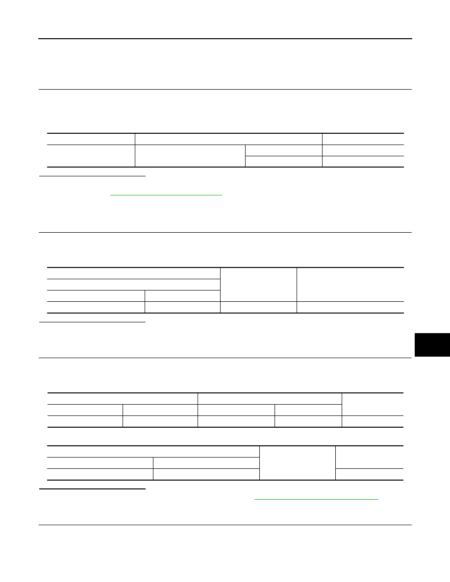
Monitor item

Condition

Status

 MAIN SW

Automatic door main switch

ON

ON

OFF

OFF

(+)

(–)

Voltage

(Approx.)

Automatic back door main switch

Connector

Terminal

M54

1

Ground

12.2 V

Automatic back door control unit

Automatic back door main switch

Continuity 

Connector

Terminal

Connector

Terminal

B24

10

M54

1

Existed

Automatic back door control unit

Ground

Continuity 

Connector

Terminal

B24

10

Not existed

DLK-162

< DTC/CIRCUIT DIAGNOSIS >

[TYPE 1]

AUTOMATIC DOOR MAIN SWITCH

Is the inspection result normal?

YES

>> GO TO 4.

NO

>> Repair or replace harness.

4.

CHECK AUTOMATIC BACK DOOR MAIN SWITCH

Refer to 

DLK-162, "Component Inspection"

.

Is the inspection result normal?

YES

>> GO TO 5.

NO

>> Replace automatic back door main switch.

5.

CHECK INTERMITTENT INCIDENT

Refer to 

GI-44, "Intermittent Incident"

.

>> INSPECTION END

Component Inspection

INFOID:0000000010708119

1.

CHECK AUTOMATIC BACK DOOR MAIN SWITCH

1.

Turn ignition switch OFF.

2.

Disconnect automatic back door main switch connector.

3.

Check continuity between automatic back door main switch terminals.

Is the inspection result normal?

YES

>> INSPECTION END

NO

>> Replace automatic back door main switch.

Automatic back door main switch

Ground

Continuity 

 Connector

Terminal

M54

3

Existed

Automatic back door main switch

 Condition

Continuity 

Terminal

1

3

Automatic back door 
main switch

ON

Existed

OFF

Not existed

AUTOMATIC BACK DOOR WARNING BUZZER

DLK-163

< DTC/CIRCUIT DIAGNOSIS >

[TYPE 1]

C

D

E

F

G

H

I

J

L

M

A

B

DLK

N

O

P

AUTOMATIC BACK DOOR WARNING BUZZER

Diagnosis Procedure

INFOID:0000000010708120

1.

CHECK AUTOMATIC BACK DOOR WARNING BUZZER POWER SUPPLY CIRCUIT

1.

Turn ignition switch OFF.

2.

Disconnect automatic back door warning buzzer connector.

3.

Check voltage between automatic back door warning buzzer harness connector and ground.

Is the inspection result normal?

YES

>> GO TO 3.

NO

>> GO TO 2.

2.

CHECK AUTOMATIC BACK DOOR WARNING BUZZER OUTPUT SIGNAL CIRCUIT

1.

Disconnect automatic back door control unit connector.

2.

Check continuity between automatic back door control unit harness connector and automatic back door
warning buzzer harness connector.

3.

Check continuity between automatic back door control unit harness connector and ground.

Is the inspection result normal?

YES

>> Replace automatic back door control unit. Refer to 

DLK-327, "Removal and Installation"

.

NO

>> Repair or replace harness.

3.

CHECK GROUND CIRCUIT

Check continuity between automatic back door warning buzzer harness connector and ground.

Is the inspection result normal?

YES

>> GO TO 4.

NO

>> Repair or replace harness.

4.

CHECK INTERMITTENT INCIDENT

Refer to 

GI-44, "Intermittent Incident"

Is the inspection result normal?

YES

>> Replace automatic back door control unit. Refer to 

DLK-327, "Removal and Installation"

.

NO

>> Repair or replace the malfunctioning parts.

Component Inspection

INFOID:0000000010708121

1.

CHECK AUTOMATIC BACK DOOR WARNING BUZZER

(+)

(–)

Voltage

(Approx.)

Automatic back door warning buzzer

 Connector

Terminal

B28

1

Ground

12 V

Automatic back door control unit

 Automatic back door warning buzzer

Continuity 

Connector

Terminal

Connector

Terminal

B25

37

B28

1

Existed

Automatic back door control unit

Ground

Continuity 

Connector

Terminal

B25

37

Not existed

Automatic back door warning buzzer

Ground

Continuity 

Connector

Terminal

B28

2

Existed

DLK-164

< DTC/CIRCUIT DIAGNOSIS >

[TYPE 1]

AUTOMATIC BACK DOOR WARNING BUZZER

1.

Turn ignition switch OFF.

2.

Disconnect automatic back door warning buzzer connector.

3.

Check battery power supply directly to automatic back door warning buzzer terminals and check the oper-
ation.

Is the inspection result normal?

YES

>> INSPECTION END

NO

>> Replace automatic back door warning buzzer.

Automatic back door warning buzzer

Operation

Terminal

(+)

(-)

1

2

Buzzer sounds


содержание   ..  453  454  455  456   ..