Nissan X-Trail 32. Manual - part 395


  Главная      Nissan     Nissan X-Trail 32 - Service Manual


поиск по сайту            


содержание   ..  393  394  395  396   ..


Nissan X-Trail 32. Manual - part 395


DAS

AROUND VIEW MONITOR CONTROL UNIT

DAS-321

< ECU DIAGNOSIS INFORMATION >

[PARK ASSIST]

C

D

E

F

G

H

I

J

K

L

M

B

N

P

A

Fail-Safe (Around View Monitor Control Unit)

INFOID:0000000010752975
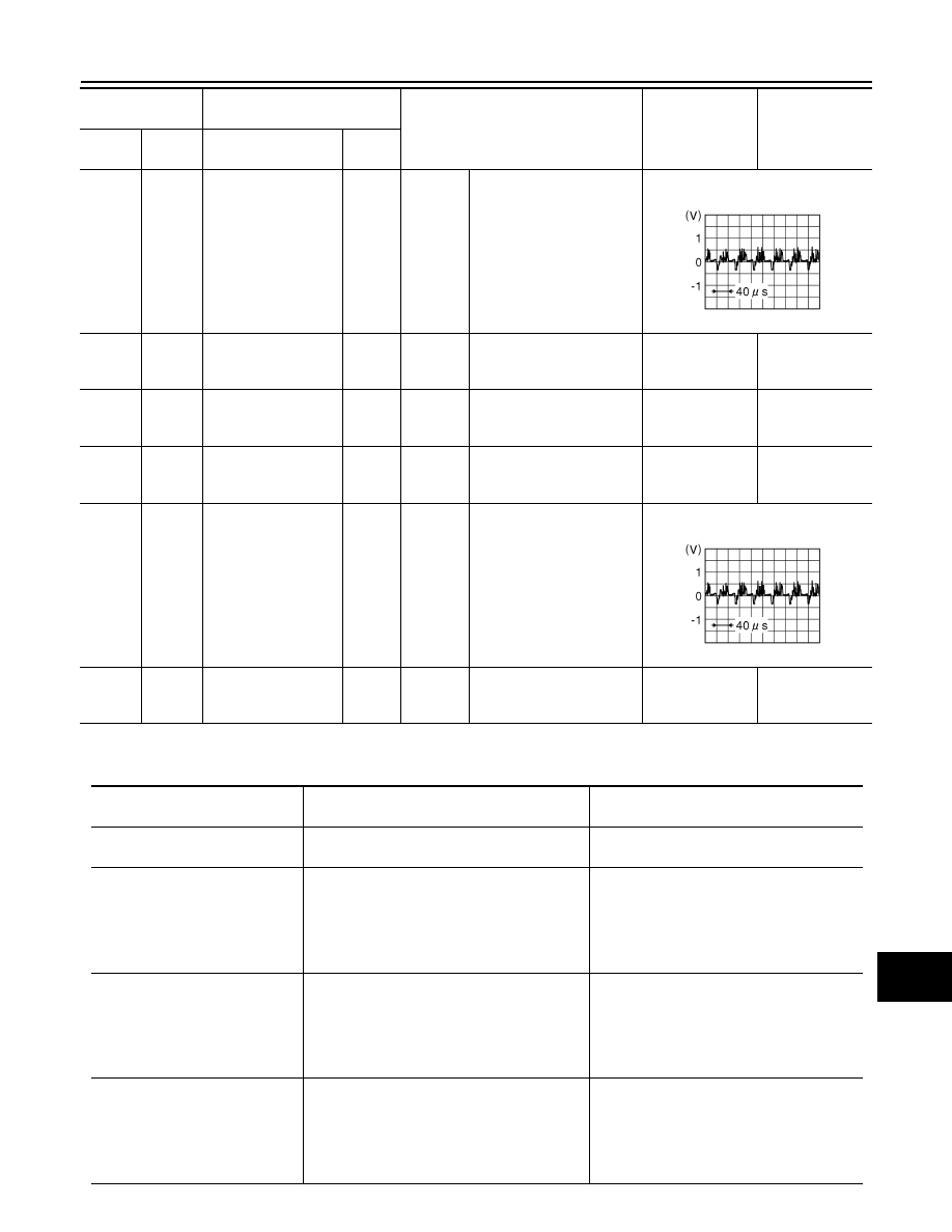
65

(Y)

66

Passenger side cam-
era image signal (+)

Input

Ignition 

switch 

ON

Input the waveform synchronized 

with the camera image signal.

66

Ground

Passenger side cam-
era image signal (

)

Ignition 

switch 

ON

0 - 0.1 V

0 V

68

(L)

70

(V)

Front camera power 
supply

Output

Ignition 

switch 

ON

5.0 - 9.0 V

6.0 V

70

(V)

Ground

Front camera ground

Ignition 

switch 

ON

0 - 0.1 V

0 V

71

(LG)

72

Front camera image 
signal (+)

Input

Ignition 

switch 

ON

Input the waveform synchronized 

with the camera image signal.

72

Ground

Front camera image 
signal (

)

Ignition 

switch 

ON

0 - 0.1 V

0 V

Terminal

(Wire color)

Description

Condition

Standard value

Reference value

(Approx.)

+

Signal name

Input/

Output

JSNIA0834GB

JSNIA0834GB

DTC

Display contents of CONSULT

Malfunction detection condition

Fail-safe condition

C1A00
CONTROL UNIT

Around view monitor control unit internal mal-
function

Around view monitor with Park Assist is can-
cel

C1A01
POWER SUPPLY CIRC

• The battery voltage sent to around view mon-

itor control unit remains less than 7.9 V for 5 
seconds

• The battery voltage sent to around view mon-

itor control unit remains more than 19.3 V for 
5 seconds

Around view monitor with Park Assist is can-
cel

C1A03
VHCL SPEED SE CIRC

If the vehicle speed signal (wheel speed) from 
ABS actuator and electric unit (control unit) re-
ceived by the around view monitor control unit 
via CAN communication, are inconsistent

• BSW system is cancel
• DAA system is stopped.
• MOD (Moving Object Detection) function is 

cancel

• Around view monitor with Park Assist is 

cancel

C1A04
ABS/TCS/VDC CIRC

If a malfunction occurs in the VDC/TCS/ABS 
system

• BSW system is cancel
• DAA system is stopped.
• MOD (Moving Object Detection) function is 

cancel

• Around view monitor with Park Assist is 

cancel

DAS-322

< ECU DIAGNOSIS INFORMATION >

[PARK ASSIST]

AROUND VIEW MONITOR CONTROL UNIT

C1A07
CVT CIRCUIT

If the CVT is malfunction

Around view monitor with Park Assist is can-
cel

C1A39
STRG SEN CIR

If the steering angle sensor is malfunction

• BSW system is cancel
• DAA system is stopped.
• MOD (Moving Object Detection) function is 

cancel

C1A56
SONAR CIRC

The around view monitor control unit detects 
that sonar control unit has a malfunction

Around view monitor with Park Assist is can-
cel

U0122
VDC P-RUN DIAGNOSIS

If around view monitor control unit detects an 
error signal that is received from ABS actuator 
and electric unit (control unit) via CAN commu-
nication

• BSW system is cancel
• DAA system is stopped.
• MOD (Moving Object Detection) function is 

cancel

• Around view monitor with Park Assist is 

cancel

U0416
VDC CHECKSUM DIAGNOSIS

If around view monitor control unit detects an 
error signal that is received from ABS actuator 
and electric unit (control unit) via CAN commu-
nication

• BSW system is cancel
• DAA system is stopped.
• MOD (Moving Object Detection) function is 

cancel

• Around view monitor with Park Assist is 

cancel

U0428
ST ANGLE SENSOR CALIBRA-
TION

Neutral position adjustment of steering angle 
sensor is not complete.

• Predicted course line is not displayed.
• MOD (Moving Object Detection) function is 

stopped.

• BSW system is stopped.
• DAA system is stopped.
• Around view monitor with Park Assist is 

stopped

U1000
CAN COMM CIRCUIT

When around view monitor control unit cannot 
transmit/receive CAN communication signal 
continuously for 2 seconds or more.

The following functions are stopped
• When communication of steering angle 

sensor signal is not normal

- Predicted course line is not displayed.
- MOD (Moving Object Detection) function is 

stopped.

- BSW system is stopped.
- DAA system is stopped.
• When communication of vehicle signal, 

wheel speed sensor signal, and shift signal 
is not normal

- Predicted course line is not displayed.
- MOD (Moving Object Detection) function is 

stopped.

- LDW system is stopped.
- BSW system is stopped.
- DAA system is stopped.
- Around view monitor with Park Assist is 

stopped

U1010
CONTROL UNIT (CAN)

CAN initial diagnosis malfunction is detected.

MOD (Moving Object Detection) function is 
stopped.

U111A
REAR CAMERA IMAGE SIGNAL

No-signal status of rear camera image signal is 
continued for 500 ms or more while ignition 
switch is ON.
NOTE:
Current malfunction is displayed only and is not 
saved.

• Camera image is not displayed (Gray 

screen display).

• MOD (Moving Object Detection) function is 

stopped.

U111B
SIDE CAMERA RH IMAGE SIG-
NAL

No-signal status of side camera RH image sig-
nal is continued for 500 ms or more while igni-
tion switch is ON.
NOTE:
Current malfunction is displayed only and is not 
saved.

Camera image is not displayed (Gray screen 
display).

DTC

Display contents of CONSULT

Malfunction detection condition

Fail-safe condition

DAS

AROUND VIEW MONITOR CONTROL UNIT

DAS-323

< ECU DIAGNOSIS INFORMATION >

[PARK ASSIST]

C

D

E

F

G

H

I

J

K

L

M

B

N

P

A

U111C
FRONT CAMERA IMAGE SIG-
NAL

No-signal status of front camera image signal is 
continued for 500 ms or more while ignition 
switch is ON.
NOTE:
Current malfunction is displayed only and is not 
saved.

Camera image is not displayed (Gray screen 
display).

U111D
SIDE CAMERA LH IMAGE SIG-
NAL

No-signal status of side camera LH image sig-
nal is continued for 500 ms or more while igni-
tion switch is ON.
NOTE:
Current malfunction is displayed only and is not 
saved.

Camera image is not displayed (Gray screen 
display).

U112F
EPS CIRCUIT

If the EPS system is malfunction

Around view monitor with Park Assist is can-
cel

U1232
ST ANGLE SEN CALIB

Neutral position adjustment of steering angle 
sensor is performed. NG signal from steering 
angle sensor is received.

• Predicted course line is not displayed.
• MOD (Moving Object Detection) function is 

stopped.

• BSW system is stopped.
• DAA system is stopped.
• Around view monitor with Park Assist is 

stopped.

U1302
CAMERA POWER VOLT

Camera power supply voltage does not satisfy 
the following conditions for 2 seconds or more 
when ignition switch is turned ON.
• When camera power supply output is ON: 5.9 

- 6.5 V

• When OFF: 0 V by camera power supply 

measurement.

Camera power output is stopped

U1304
CAMERA IMAGE CALIB

• When camera calibration is incomplete.
• When camera information in around view 

monitor control unit and information read 
from camera are not the same.

NOTE:
Current malfunction is displayed only and is not 
saved.

• Unmatched icon 

 display (red) is dis-

played (applicable for unmatched camera 
only).

• Around view monitor with Park Assist is 

cancel.

U1305
CONFIG UNFINISH

The vehicle setting of around view monitor con-
trol unit is incomplete.
NOTE:
Current malfunction is displayed only and is not 
saved.

• On applicable camera screen 

 marking 

(Red) is displayed.

• Around view monitor with Park Assist is 

cancel.

U1308
R-CAMERA (R&L) CALIB JDG-
MNT

Camera image calibration is incomplete

• MOD (Moving Object Detection) function is 

stopped.

• BSW system is stopped.
• Around view monitor with Park Assist is 

stopped.

U1309
PUMP INPUT CURRENT JUDGE

Around view monitor control unit detects the 
value of current from pump control unit is incor-
rect

BSW system is stopped.

U130A PUMP ECU JUDGE

If the pump control unit is malfunction

BSW system is stopped.

U130B
RR CAMERA COMM ERROR

Around view monitor control unit receives the 
incorrect communication signal from rear view 
camera

• MOD (Moving Object Detection) function is 

stopped.

• BSW system is stopped.

U1320
REPROGRAMMING

Reprogramming of around view monitor control 
unit is incomplete

Around view monitor with Park Assist is can-
cel

U150E
BCM CIRCUIT

If the BCM is malfunction

Around view monitor with Park Assist is can-
cel

DTC

Display contents of CONSULT

Malfunction detection condition

Fail-safe condition

DAS-324

< ECU DIAGNOSIS INFORMATION >

[PARK ASSIST]

AROUND VIEW MONITOR CONTROL UNIT

DTC Inspection Priority Chart

INFOID:0000000010752976

If multiple DTCs are detected simultaneously, check them one by one depending on the following DTC inspec-
tion priority chart.

DTC Index

INFOID:0000000010752977

Fail-safe subject system

• A: Around View Monitor system
• B: MOD (Moving Object Detection)
• C: BSW (Blind Spot Warning)
• D: DAA (Driver Attention Alert)
• E: Around view monitor with Park Assist

U1971
SONAR MESSAGE COUNTER 
DIAG

Around view monitor control unit receives an in-
correct signal from sonar control unit via CAN 
communication

Around view monitor with Park Assist is can-
cel

U1972
EPS MESSAGE COUNTER DIAG

Around view monitor control unit receives an in-
correct signal from EPS control unit via CAN 
communication

Around view monitor with Park Assist is can-
cel

Other

When around view monitor control unit is not 
normal.

Switch to camera screen is not allowed.

DTC

Display contents of CONSULT

Malfunction detection condition

Fail-safe condition

Priority

Detected items (DTC)

1

U1305: CONFIG UNFINISH

2

U1320: REPROGRAMMING

3

• U1000: CAN COMM CIRCUIT
• U1010: CONTROL UNIT (CAN)

4

• U1232: ST ANGLE SEN CALIB
• U1304: CAMERA IMAGE CALIB

5

• U0428: ST ANGLE SENSOR CALIBRATION

6

• U130B: RR CAMERA COMM ERROR

7

• U1308: R-CAMERA (R&L) CALIB JDGMNT

8

• C1A01: POWER SUPPLY VOLTAGE CIRCUIT 1
• C1A04: ABS/TCS/VDC CIRC
• C1A07: CVT SYSTEM
• C1A39: STRG SEN CIR
• C1B56: SONAR SYSTEM
• U0122: VDC P-RUN DIAGNOSIS
• U0416: VDC CHECKSUM DIAGNOSIS
• U111A: REAR CAMERA IMAGE SIGNAL
• U111B: SIDE CAMERA RH IMAGE SIGNAL
• U111C: FRONT CAMERA IMAGE SIGNAL
• U111D: SIDE CAMERA LH IMAGE SIGNAL
• U112F: EPS SYSTEM
• U1302: CAMERA POWER SUPPLY VOLTAGE
• U1304: CAMERA CALIBRATION
• U1309: PUMP INPUT CURRENT JUDGE
• U130A: PUMP ECU JUDGE
• U150E: BCM SYSTEM
• U1971: SONAR MESSAGE COUNTER DIAGNOSIS
• U1972: EPS MESSAGE COUNTER DIAGNOSIS

9

• C1A00: CONTROL UNIT
• C1A03: VHCL SPEED SE CIRC


содержание   ..  393  394  395  396   ..