Nissan X-Trail 32. Manual - part 287


  Главная      Nissan     Nissan X-Trail 32 - Service Manual


поиск по сайту            


содержание   ..  285  286  287  288   ..


Nissan X-Trail 32. Manual - part 287


CL-16

< REMOVAL AND INSTALLATION >

CLUTCH PEDAL

INSTALLATION

Note the following, and install in the reverse order of removal.
• Push clip until it clicks.
• Press master cylinder rod end to pin of clutch pedal until it stops.
• Perform inspection and adjustment after installation. Refer to 

CL-16, "LHD : Inspection and Adjustment"

.

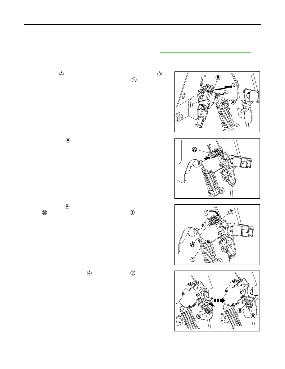
• Install clutch pedal stroke sensor, according to the following procedure.

CAUTION:

Install clutch pedal position switch before installing clutch pedal stroke sensor.

1.

Insert pawl 

 into the hole and hook it, and fit lever pin 

 into

the hole. And then clutch pedal stroke sensor 

 is installed tem-

porary.

2.

Push lever pin 

 and insert it into the hole deeply.

3.

Turn lever pin 

 as shown in the figure and fix lever pin to stop-

per 

. And then clutch pedal stroke sensor 

 is installed com-

pletely.

4.

Push sensor lever cover 

, then hold on pin 

 of clutch pedal.

LHD : Inspection and Adjustment

INFOID:0000000010745327

INSPECTION AFTER REMOVAL

JSDIA5601ZZ

JSDIA5602ZZ

JSDIA5603ZZ

JSDIA5604ZZ

CLUTCH PEDAL

CL-17

< REMOVAL AND INSTALLATION >

C

E

F

G

H

I

J

K

L

M

A

B

CL

N

O

P

• Check clutch pedal for bend, damage, or a cracked weld. If bend, damage, or a cracked weld is found,

replace clutch pedal assembly.

• Check pedal stopper rubber 

. If damage or deformation is found,

replace clutch pedal assembly.

• Check pedal pad 

. If wear or damage is found, replace clutch

pedal assembly.

INSPECTION AFTER INSTALLATION

• Check the clutch pedal height, clutch pedal height at clutch disengagement, and clutch pedal play. Refer to

CL-9, "Inspection and Adjustment"

.

• Check the clutch pedal position switch position. Refer to 

CL-9, "Inspection and Adjustment"

.

• Check the clutch interlock switch position. Refer to 

CL-9, "Inspection and Adjustment"

.

ADJUSTMENT AFTER INSTALLATION

• Adjust the clutch pedal position switch position. Refer to 

CL-9, "Inspection and Adjustment"

.

• Adjust the clutch interlock switch position. Refer to 

CL-9, "Inspection and Adjustment"

.

• Perform reset of clutch pedal stroke sensor, after installation clutch pedal or clutch pedal stroke sensor.

Refer to 

PB-59, "Work Procedure"

.

RHD

JSDIA6112ZZ

JSDIA6113ZZ

CL-18

< REMOVAL AND INSTALLATION >

CLUTCH PEDAL

RHD : Exploded View

INFOID:0000000010745328

RHD : Removal and Installation

INFOID:0000000010745329

REMOVAL

1.

Remove instrument lower panel RH. Refer to 

IP-41, "Removal and Installation"

.

2.

Disconnect clutch pedal position switch harness connector.

3.

Disconnect clutch interlock switch harness connector.

4.

Disconnect clutch pedal stroke sensor harness connector.

5.

Disconnect harness clip from clutch pedal bracket 

.

Clutch pedal assembly

Clutch pedal stroke sensor

Clutch pedal position switch

Clip

Pedal pad

Clutch interlock switch

: N·m (kg-m, ft-lb)

JSDIA5585GB

: Hole for harness clip

JSDIA6110ZZ

CLUTCH PEDAL

CL-19

< REMOVAL AND INSTALLATION >

C

E

F

G

H

I

J

K

L

M

A

B

CL

N

O

P

6.

Remove clutch pedal stroke sensor 

.

a.

Pull sensor lever cover 


b.

While turn lever pin 

 and pull it.

c.

Remove clutch pedal stroke sensor.

7.

Remove master cylinder rod end from clutch pedal lever 

.

8.

Remove clutch pedal position switch 

 and clip 

 from clutch

pedal bracket.

9.

Remove clutch interlock switch 

 and clip 

 from clutch pedal

bracket.

10. Remove clutch pedal assembly.
11. Remove pedal pad from clutch pedal.

12. Perform inspection after removal. Refer to 

CL-20, "RHD :

Inspection and Adjustment"

.

JSDIA5591ZZ

JSDIA6109ZZ

JSDIA5592ZZ

JSDIA5593ZZ

JSDIA5594ZZ


содержание   ..  285  286  287  288   ..