содержание .. 281 282 283 284 ..
Nissan X-Trail 32. Manual - part 283
CHG-48
< SERVICE DATA AND SPECIFICATIONS (SDS)
[TYPE 2]
SERVICE DATA AND SPECIFICATIONS (SDS)
SERVICE DATA AND SPECIFICATIONS (SDS)
SERVICE DATA AND SPECIFICATIONS (SDS)
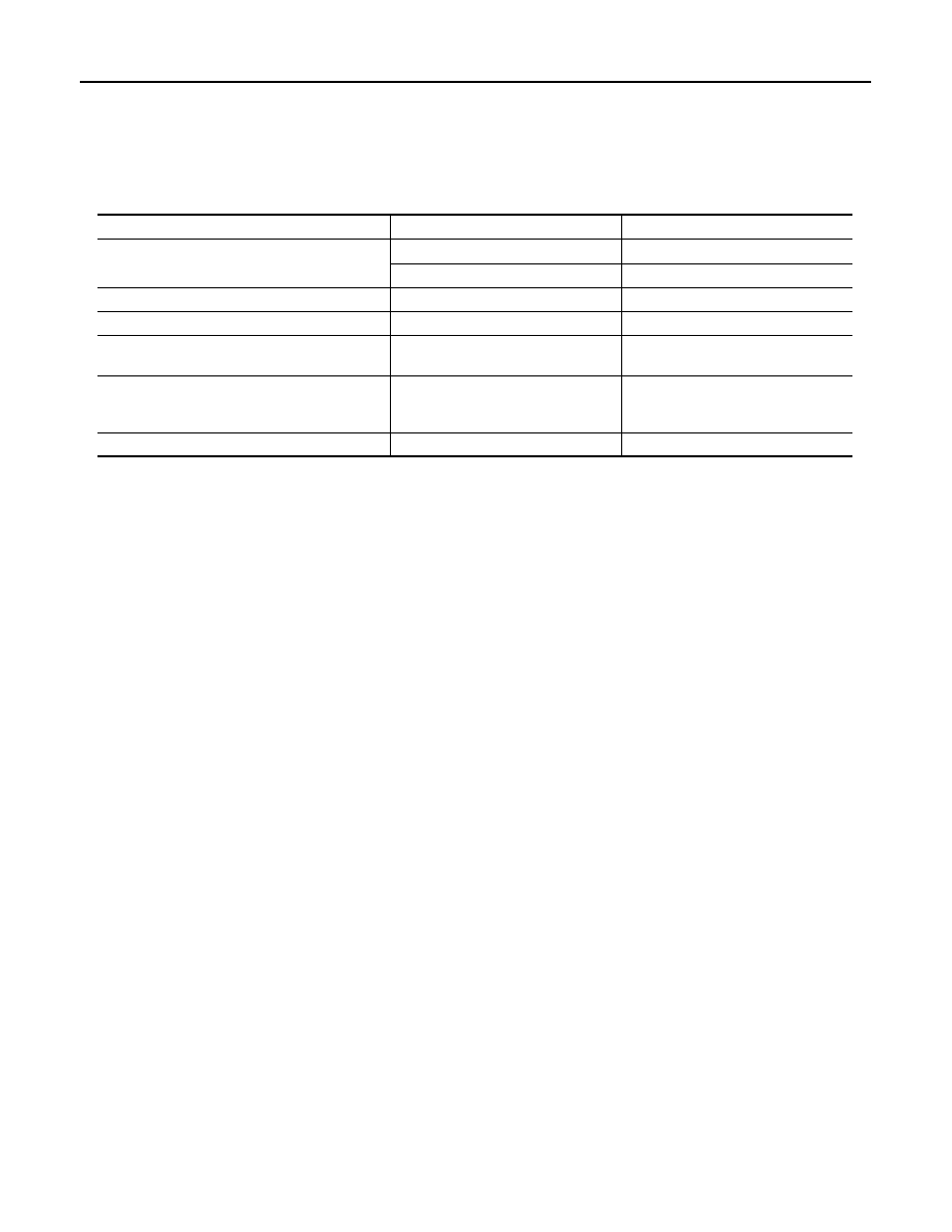
Alternator
INFOID:0000000010957591
Applied model
MR engine
QR engine
Type
2620093
2620168
Valeo Make
Valeo Make
Nominal rating
[V - A]
12 - 120
12 - 120
Ground polarity
Negative
Negative
Minimum revolution under no-load
(When 13.5 V is applied)
[rpm]
Less than 1,200
Less than 1,200
Hot output current
(When 13.5 V is applied)
[A/rpm]
More than 46/1,500
More than 96/2,500
More than 117/5,000
More than 46/1,500
More than 96/2,500
More than 117/5,000
Regulated output voltage
[V]
14.0 – 14.6
14.0 – 14.6