Nissan X-Trail 32. Manual - part 277


  Главная      Nissan     Nissan X-Trail 32 - Service Manual


поиск по сайту            


содержание   ..  275  276  277  278   ..


Nissan X-Trail 32. Manual - part 277


CHG-24

< DTC/CIRCUIT DIAGNOSIS >

[TYPE 1]

B TERMINAL CIRCUIT

B TERMINAL CIRCUIT

Diagnosis Procedure

INFOID:0000000010957612

1.

CHECK “B” TERMINAL CONNECTION

1.

Turn ignition switch OFF.

2.

Check if “B” terminal is clean and tight.

Is the inspection result normal?

YES

>> GO TO 2.

NO

>> Repair “B” terminal connection.

2.

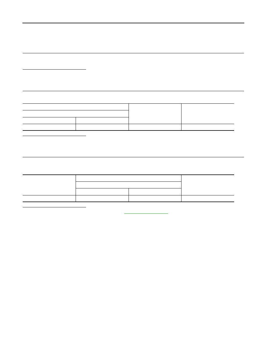
CHECK “B” TERMINAL CIRCUIT

Check voltage between alternator “B” terminal and ground.

Is the inspection result normal?

YES

>> GO TO 3.

NO

>> Check harness for open between alternator and fusible link.

3.

CHECK “B” TERMINAL CONNECTION (VOLTAGE DROP TEST)

1.

Start engine, then engine running at idle and warm.

2.

Check voltage between battery positive terminal and alternator “B” terminal.

Is the inspection result normal?

YES

>> “B” terminal circuit is normal. Refer to 

CHG-14, "Work Flow"

.

NO

>> Check harness between battery and alternator for poor continuity.

(+)

(–)

Voltage (Approx.)

Alternator

Connector

Terminal

F131

1

Ground

Battery voltage

(+)

(–)

Voltage (Approx.)

Alternator

Connector

Terminal

Battery positive terminal

F131

Less than 0.2 V

CHG

CHARGING SYSTEM

CHG-25

< SYMPTOM DIAGNOSIS >

[TYPE 1]

C

D

E

F

G

H

I

J

K

L

B

A

O

P

N

SYMPTOM DIAGNOSIS

CHARGING SYSTEM

Symptom Table

INFOID:0000000010957613

Symptom

Reference

Discharged battery

Refer to 

CHG-14, "Work Flow"

.

The charge warning lamp does not turn OFF after the engine 
starts.

CHG-26

< REMOVAL AND INSTALLATION >

[TYPE 1]

ALTERNATOR

REMOVAL AND INSTALLATION

ALTERNATOR

R9M

R9M : Exploded View

INFOID:0000000010728733

R9M : Removal and Installation

INFOID:0000000010728734

REMOVAL

1.

Disconnect battery cable from negative terminal. Refer to 

PG-139, "R9M : Removal and Installation"

.

2.

Remove drive belt. Refer to 

EM-300, "Removal and Installation"

.

3.

Remove air duct (inlet). Refer to 

EM-308, "Removal and Installation"

.

4.

Remove electric throttle control actuator. Refer to 

EM-314, "Removal and Installation"

.

CAUTION:

Cover the openings to avoid entry of foreign materials.

5.

Remove electric throttle control actuator bracket mounting nut 
and bolt 

, and then remove electric throttle control actuator

bracket .

6.

Remove air inlet hose 2. Refer to 

EM-310, "Removal and Installation"

.

Alternator mounting bolt

Alternator

“B” terminal harness

“B” terminal nut

Alternator bracket

Alternator connector

: N·m (kg-m, ft-lb)

JMMIA1609GB

JMMIA1822ZZ

CHG

ALTERNATOR

CHG-27

< REMOVAL AND INSTALLATION >

[TYPE 1]

C

D

E

F

G

H

I

J

K

L

B

A

O

P

N

7.

Remove air inlet tube 2 mounting bolt 

 and disconnect air inlet

tube 2 

 from charge air cooler, and then get air inlet tube 2 out

of alternator removal area.

8.

Remove solenoid valve and bracket assembly.

a.

Remove water hose fixing clip 

 from solenoid valve bracket.

b.

Disconnect vacuum hose 

 and 

 from solenoid valve.

c.

Disconnect solenoid valve connector 

.

d.

Remove solenoid valve harness fixing clips 

 from solenoid

valve bracket.

e.

Remove mounting bolts 

 and 

, and then remove solenoid

valve 

 and bracket assembly 

 as a set.

9.

Remove oil level gauge and oil level gauge guide. Refer to 

EM-330, "Exploded View"

.

CAUTION:

Cover the openings to avoid entry of foreign materials.

10. Disconnect alternator connector.

11. Remove “B” terminal nut and disconnect “B” terminal harness.

12. Remove alternator mounting bolts.
13. Remove alternator upward from the vehicle.

CAUTION:

Never contact with and damage surrounding parts when removing alternator from the vehicle.

INSTALLATION

JMMIA1821ZZ

: Vehicle front

JMMIA0964ZZ

: Vehicle front

JMMIA0965ZZ

: Vehicle front

JMMIA0966ZZ


содержание   ..  275  276  277  278   ..