содержание .. 273 274 275 276 ..
Nissan X-Trail 32. Manual - part 275
CHG-16
< DTC/CIRCUIT DIAGNOSIS >
[TYPE 1]
B20BD BATTERY CURRENT SENSOR
DTC/CIRCUIT DIAGNOSIS
B20BD BATTERY CURRENT SENSOR
DTC Description
INFOID:0000000010957606
DTC DETECTION LOGIC
POSSIBLE CAUSE
[CIRC SHORT TO GRND]
• Harness or connectors
- Battery current sensor input signal (Current) circuit is shorted (Ground)
- Battery current sensor power circuit is open
• Battery current sensor
[CIRC SHORT TO BATTERY]
• Harness or connectors
- Battery current sensor input signal (Current) circuit is shorted (Power)
• Battery current sensor
[CIRC OPEN] or [CMPNENT INTERNAL MLFNCTN]
• Battery terminal is not connected
• Harness or connectors
- Battery current sensor input circuit is open
• Battery current sensor
FAIL-SAFE
Stop/start system is inhibited when this DTC is detected.
DTC CONFIRMATION PROCEDURE
1.
PERFORM COMPONENT FUNCTION CHECK
1.
Start engine and wait for 10 seconds or more.
2.
Perform “Self Diagnostic Result” mode of “IPDM E/R” using CONSULT.
Is the inspection result normal?
YES-1 >> To check malfunction symptom before repair: Refer to
GI-44, "Intermittent Incident"
.
YES-2 >> Confirmation after repair: INSPECTION END
NO
>> Proceed to
Diagnosis Procedure
INFOID:0000000010957607
1.
CHECK DTC
Perform each inspection according to the displayed DTC.
Which DTC is displayed?
[CIRC SHORT TO GRND]>>GO TO 2.
[CIRC SHORT TO BATTERY]>>GO TO 7.
[CIRC OPEN] or [CMPNENT INTERNAL MLFNCTN]>>GO TO 8.
2.
CHECK BATTERY CURRENT SENSOR POWER
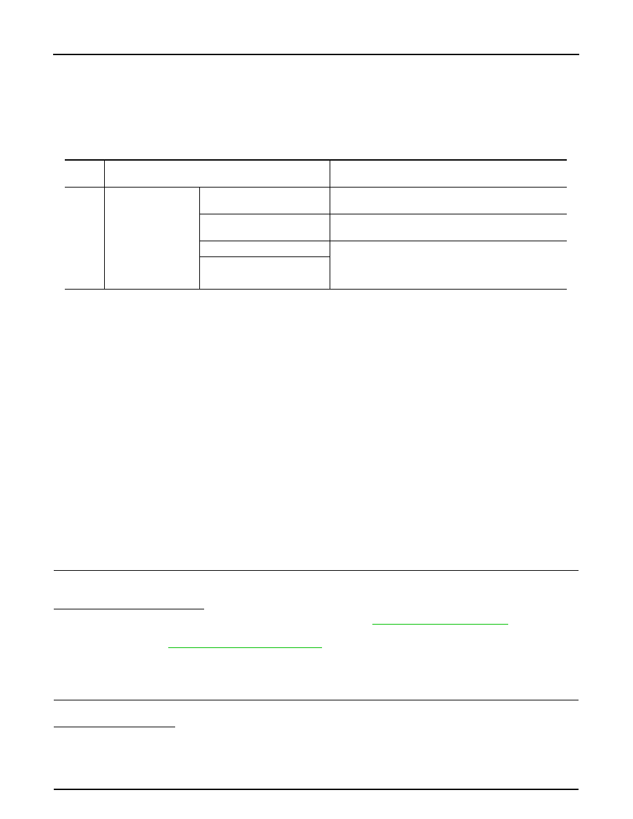
DTC
No.
CONSULT screen terms
(Trouble diagnosis content)
DTC detecting condition
B20BD
CURRENT SENSOR
(Current sensor)
[CIRC SHORT TO GRND]
An excessively low voltage from the sensor is sent to IPDM
E/R.
[CIRC SHORT TO BATTERY]
An excessively high voltage from the sensor is sent to IPDM
E/R.
[CIRC OPEN]
The output voltage of the battery current sensor is lower
than the specified value while the battery voltage is high
enough or the changing of voltage is lower than the speci-
fied value.
[CMPNENT INTERNAL
MLFNCTN]