содержание .. 271 272 273 274 ..
Nissan X-Trail 32. Manual - part 273
CHG-8
< SYSTEM DESCRIPTION >
[TYPE 1]
SYSTEM
SYSTEM
ENERGY MANAGEMENT SYSTEM
ENERGY MANAGEMENT SYSTEM : System Description
INFOID:0000000010957601
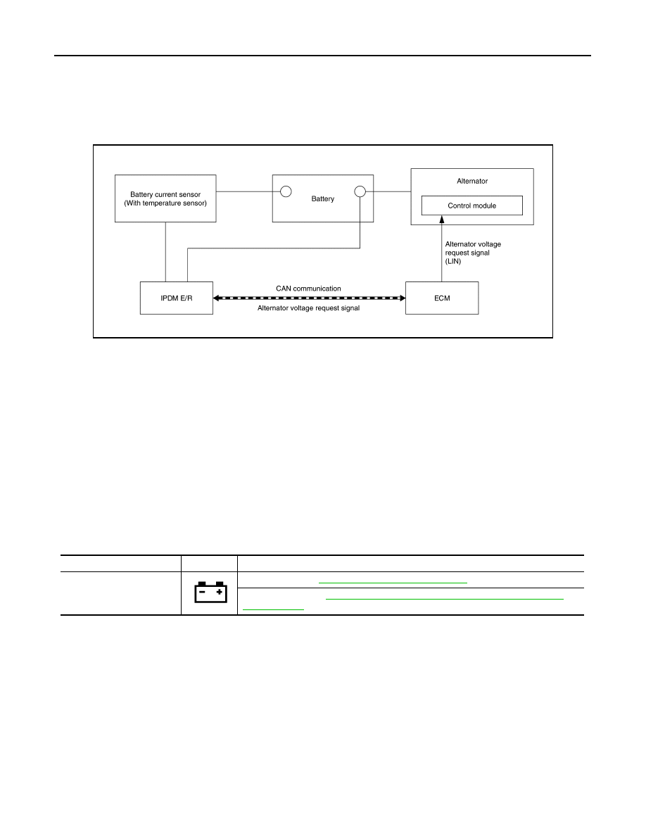
SYSTEM DIAGRAM
SYSTEM DESCRIPTION
• Battery current sensor (With battery temperature sensor) measures the charging/discharging current of the
battery and the temperature around the battery.
• IPDM E/R judges battery condition according to the charging/discharging current of the battery and the tem-
perature around the battery.
• IPDM E/R calculates the target power generation voltage according to the battery condition and sends the
calculated value as alternator voltage request signal to ECM via CAN communication.
• ECM transmits alternator voltage request signal to alternator via LIN communication.
• Control module inside alternator controls the power generation voltage based on the received alternator volt-
age request signal.
• Alternator includes a self-diagnosis function and transmits the diagnosis result to ECM via LIN communica-
tion when detecting any malfunction.
WARNING/INDICATOR/CHIME LIST
WARNING/INDICATOR/CHIME LIST : Warning Lamps/Indicator Lamps
INFOID:0000000010957634
JMMIA1835GB
Item
Design
Reference
Charge warning lamp
For layout, refer to
MWI-10, "METER SYSTEM : Design"
MWI-30, "WARNING LAMPS/INDICATOR LAMPS : Charge
.