Nissan X-Trail 32. Manual - part 2226


  Главная      Nissan     Nissan X-Trail 32 - Service Manual


поиск по сайту            


содержание   ..  2224  2225  2226  2227   ..


Nissan X-Trail 32. Manual - part 2226


COMPONENT PARTS

WW-11

< SYSTEM DESCRIPTION >

C

D

E

F

G

H

I

J

K

M

A

B

WW

N

O

P

*

1

: For models with light & rain sensor

*

2

: For M/T models

*

3

: Except for M/T models
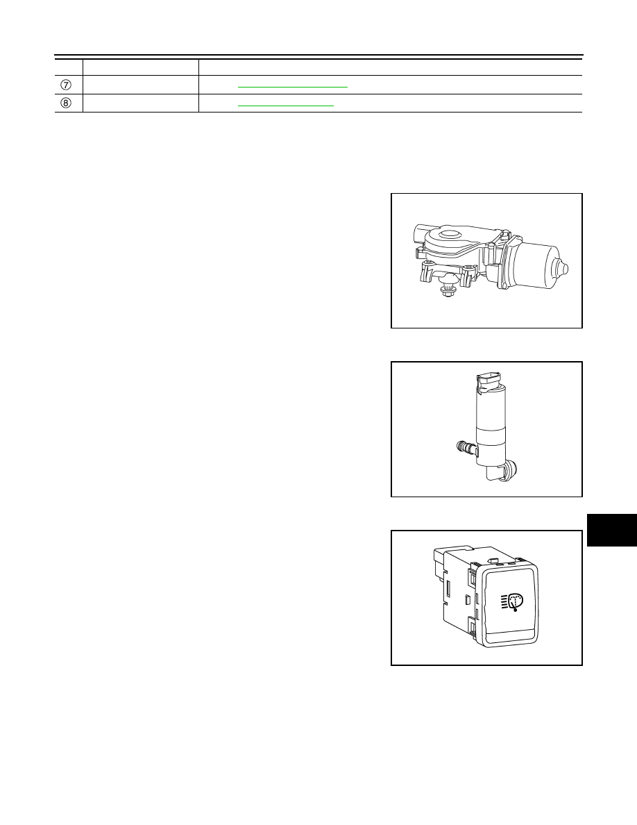
Front Wiper Motor

INFOID:0000000010785407

• Controls front wiper operation with IPDM E/R control.
• Transmits front wiper stop position signal to IPDM E/R.

Headlamp Washer Pump

INFOID:0000000010957667

Washer fluid is sprayed according to the power supply from head-
lamp washer relay.

Headlamp Washer Switch

INFOID:0000000010957668

When headlamp washer switch is pressed, headlamp washer switch
transmits the switch status to BCM.

Rear wiper motor

Refer to 

WW-12, "Rear Wiper Motor"

.

Washer pump

Refer to 

WW-12, "Washer Pump"

.

No.

Component

Function

JMLIA2397ZZ

JMLIA3076ZZ

JMLIA5392ZZ

WW-12

< SYSTEM DESCRIPTION >

COMPONENT PARTS

Light & Rain Sensor

INFOID:0000000010785408

Detects water droplets on the windshield with infrared rays, and
transmits the light & rain sensor signal to BCM via the light & rain
sensor serial link.

Rear Wiper Motor

INFOID:0000000010785409

• Controls rear wiper operation with BCM control.
• Transmits rear wiper stop position signal to BCM.

Washer Switch

INFOID:0000000010785410

• Washer switch is integrated with combination switch.
• Combination switch operates front washer or rear washer by changing voltage polarity to be supplied to

washer pump.

Washer Pump

INFOID:0000000010785411

Washer fluid is sprayed according to washer switch states.

JSLIA0093ZZ

JMLIA2398ZZ

JPLIA0163GB

JMLIA2396ZZ

SYSTEM

WW-13

< SYSTEM DESCRIPTION >

C

D

E

F

G

H

I

J

K

M

A

B

WW

N

O

P

SYSTEM

FRONT WIPER AND WASHER SYSTEM (WITH LIGHT & RAIN SENSOR) 

FRONT WIPER AND WASHER SYSTEM (WITH LIGHT & RAIN SENSOR)  : System 
Description

INFOID:0000000010785412

SYSTEM DIAGRAM

OUTLINE

The front wiper is controlled by each function of BCM and IPDM E/R.

Control by BCM

• Combination switch reading function
• Front wiper control function

Control by IPDM E/R

• Front wiper control function
• Relay control function

FRONT WIPER BASIC OPERATION

• BCM detects the combination switch condition by the combination switch reading function.
• BCM transmits the front wiper request signal to IPDM E/R via CAN communication depending on each oper-

ating condition of the front wiper.

• IPDM E/R turns ON/OFF the integrated front wiper relay and the front wiper HI/LO relay according to the

front wiper request signal. IPDM E/R provides the power supply to operate the front wiper HI/LO operation.

FRONT WIPER LO OPERATION

• BCM transmits the front wiper request signal (LOW) to IPDM E/R via CAN communication according to the

front wiper LO operating condition.

Front wiper LO operating condition

- Ignition switch ON
- Front wiper switch LO or front wiper switch MIST (while pressing)
• IPDM E/R turns ON the integrated front wiper relay according to the front wiper request signal (LOW).

FRONT WIPER HI OPERATION

• BCM transmits the front wiper request signal (HIGH) to IPDM E/R via CAN communication according to the

front wiper HI operating condition.

Front wiper HI operating condition

- Ignition switch ON
- Front wiper switch HI
• IPDM E/R turns ON the integrated front wiper relay and the front wiper HI/LO relay according to the front

wiper request signal (HIGH).

FRONT WIPER AUTO OPERATION

JMLIA5501GB

WW-14

< SYSTEM DESCRIPTION >

SYSTEM

Rain Detection

Rain level and sensor conditions are detected by light & rain sensor.
• BCM transmits the vehicle conditions (vehicle speed, front wiper condition, light & rain sensor sensitivity set-

ting, etc.) to the light & rain sensor via the light & rain sensor serial link.

• Light & rain sensor judges a wiping speed for front wiper by rain condition and the vehicle conditions. And it

transmits the wiping speed request signal to the BCM via the light & rain sensor serial link.

Auto Wiping Operation 

• BCM receives the wiping speed request signal from the light & rain sensor via the light & rain sensor serial

link.

• BCM controls front wiper operation according to the wiping speed request signal. And it transmits the front

wiper request signal (LOW or HIGH) to the IPDM E/R via CAN communication line.

Front wiper AUTO operating condition

- Ignition switch ON
- Front wiper switch AUTO
NOTE:
When the front wiper switch is turned to AUTO position, front wiper operates once regardless of rainy condi-
tions.

Light & rain Sensor Sensitivity Setting

BCM determines light & rain sensor sensitivity according to wiper volume dial position.

NOTE:
Factory setting of the light & rain sensor operation is operation linked with light & rain sensor. Light & rain sen-
sor operation can be set to operation linked or not linked with light & rain sensor using CONSULT. Refer to

WW-29, "WIPER : CONSULT Function - WIPER"

.

NOTE:
When the wiper volume dial position is turned up by 1 level under front wiper AUTO operating condition, front
wiper operates once.

Splash mode operation

Front wiper is operated at HI regardless of the wiper volume adjustment position, when water drops are instan-
taneously sprayed over the windshield glass due to water splash from oncoming vehicles or other causes.
After that, AUTO operation is performed depending on the amount of water drops.

SPLASH MODE OPERATION CONDITIONS

• Front wiper switch AUTO
• Ignition switch ON
NOTE:
Splash mode is not operated and auto wiping operation is performed, while the vehicle is stopped.

FRONT WIPER AUTO STOP OPERATION

• BCM transmits the front wiper request signal (RETURN) to IPDM E/R via CAN communication when the

front wiper switch is turned OFF.

• IPDM E/R detects the front wiper stop position signal from the front wiper motor to find out the front wiper

motor position (stop position/except stop position).

• When IPDM E/R receives the front wiper request signal (RETURN) from BCM and the front wiper motor

position is not in the stop position, IPDM E/R turns ON the front wiper relay until the front wiper motor returns
to the stop position.

• When the front wiper motor returns to the stop position, IPDM E/R transmits front wiper status signal to BCM

via CAN communication.

• When BCM receives front wiper status signal from IPDM E/R, BCM transmits the front wiper request signal

(STOP) to IPDM E/R via CAN communication.

FRONT WIPER OPERATION LINKED WITH WASHER

Wiper volume dial position

Sensitivity

1

Low sensitivity

2

Low

medium sensitivity

3

Medium

high sensitivity

4

High sensitivity


содержание   ..  2224  2225  2226  2227   ..