содержание .. 2167 2168 2169 2170 ..
Nissan X-Trail 32. Manual - part 2169
TM-634
< DTC/CIRCUIT DIAGNOSIS >
[CVT: RE0F10G]
P188E ELECTRIC OIL PUMP
Is the inspection result normal?
YES
>> GO TO 5.
NO
>> Repair or replace malfunctioning parts.
5.
CHECK ELECTRIC OIL PUMP RELAY SIGNAL
1.
Install the electric oil pump relay.
2.
Connect the TCM connector.
3.
Check the voltage between the TCM harness connector terminal and ground.
Is the inspection result normal?
YES
>> GO TO 6.
NO
TM-676, "Removal and Installation"
6.
CHECK TCM COMMAND SIGNAL
With CONSULT
1.
Turn ignition switch ON.
2.
Select “Data Monitor” in “TRANSMISSION”.
3.
Select “ELECTRIC OP DUTY”.
4.
Start the engine.
5.
Drive the vehicle and maintain the following condition.
6.
Activate stop/start system. Refer to.
EC-856, "STOP/START SYSTEM : System Description (CVT mod-
Is the inspection result normal?
YES
>> GO TO 7.
NO
TM-676, "Removal and Installation"
7.
CHECK ELECTRIC OIL PUMP STATUS SIGNAL
With CONSULT
1.
Turn ignition switch OFF.
2.
Turn ignition switch ON.
3.
Select “E-OP DUTY MON”.
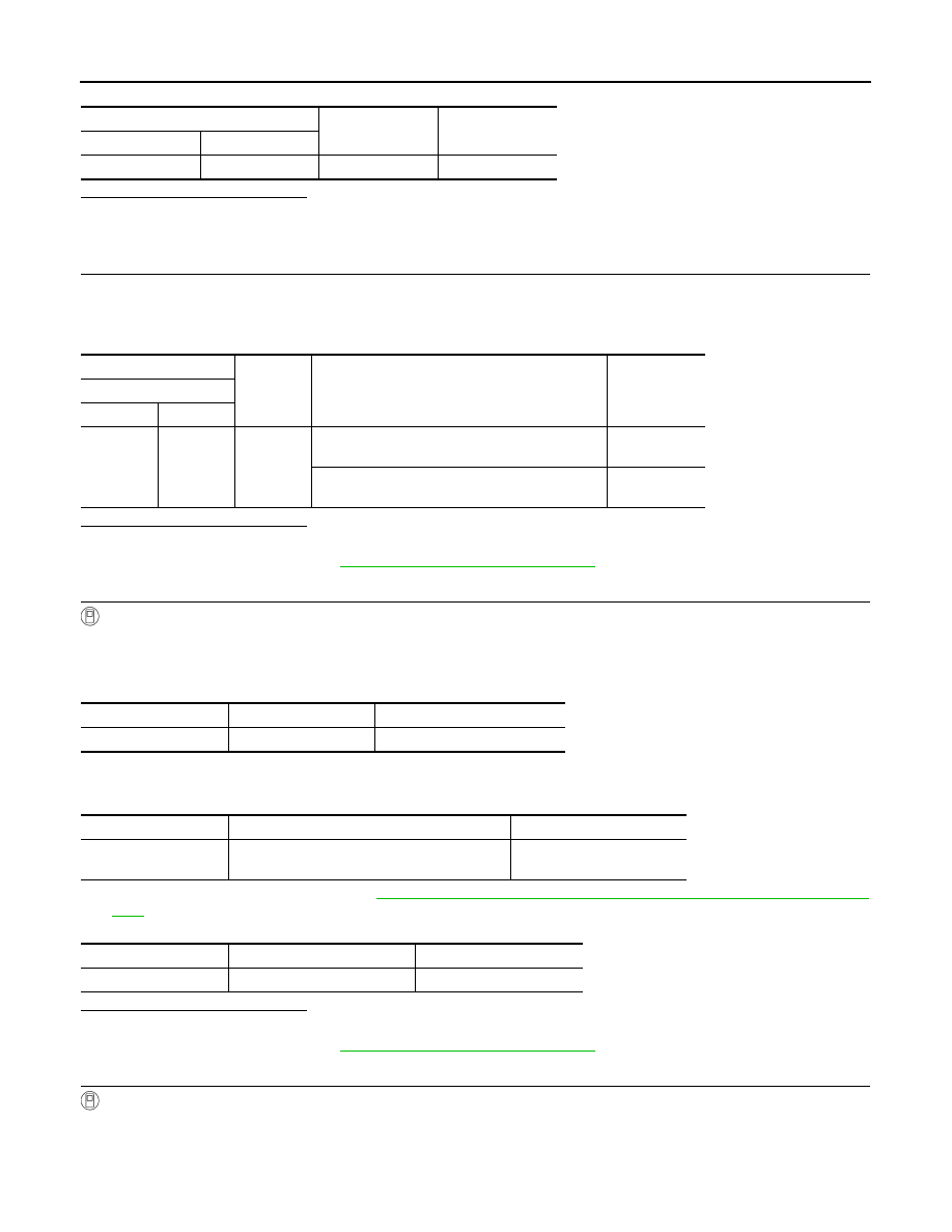
Electric oil pump relay
—
Continuity
Connector
Terminal
F66
2
Ground
Not existed
+
−
Condition
Voltage
TCM
Connector
Terminal
F119
1
Ground
• Selector lever: “D”position
• Vehicle speed: 11 km/h (7 MPH) or more
10 – 16 V
• Selector lever: “D”position
• Vehicle speed: 6 km/h (3 MPH) or less
Approx. 0 V
Monitor item
Condition
Reference value/Status
ELECTRIC OP DUTY
Ignition switch: ON
5 – 15%
Monitor item
Condition
Reference value/Status
ELECTRIC OP DUTY
• Selector lever: “D”position
• Vehicle speed: 11 km/h (7 MPH) or more
5 – 15%
Monitor item
Condition
Reference value/Status
ELECTRIC OP DUTY
Stop/start system operating
55 – 85%