содержание .. 2166 2167 2168 2169 ..
Nissan X-Trail 32. Manual - part 2168
TM-630
< DTC/CIRCUIT DIAGNOSIS >
[CVT: RE0F10G]
P1588 G SENSOR
YES
>> Go to
NO-1
>> To check malfunction symptom before repair: Refer to
GI-44, "Intermittent Incident"
.
NO-2
>> Confirmation after repair: INSPECTION END
Diagnosis Procedure
INFOID:0000000010646393
1.
CHECK G SENSOR SIGNAL
With CONSULT
1.
Park the vehicle on a level surface.
2.
Turn ignition switch ON.
3.
Select “Data Monitor” in “TRANSMISSION”
4.
Select “G SEN SLOPE”.
5.
Swing the vehicle and check if value varies between
−
40.45% and 40.45%.
Is the inspection result normal?
YES
>> GO TO 2.
NO
>> GO TO 3.
2.
G SENSOR CALIBRATION (PART 1)
With CONSULT
1.
Select “Self Diagnostic Results” in “TRANSMISSION”.
2.
Touch “Erase”.
>> Perform “G SENSOR CALIBRATION”. Refer to
3.
CHECK G SENSOR
1.
Remove G sensor.
TM-678, "Removal and Installation"
.
2.
Connect the all connectors.
3.
Turn ignition switch ON.
4.
Check voltage between TCM harness connector terminal and
ground.
Is the inspection result normal?
YES
>> GO TO 4.
NO
>> Replace G sensor.
TM-678, "Removal and Installation"
.
4.
G SENSOR CALIBRATION (PART 2)
With CONSULT
1.
Install G sensor.
TM-678, "Removal and Installation"
.
2.
Select “Self Diagnostic Results” in “TRANSMISSION”.
3.
Touch “Erase”.
Monitor item
Condition
Standard
G SEN SLOPE
Flat road
0%
Uphill
Positive value (Maximum 40.45%)
Downhill
Negative value (Minimum
−
40.45%)
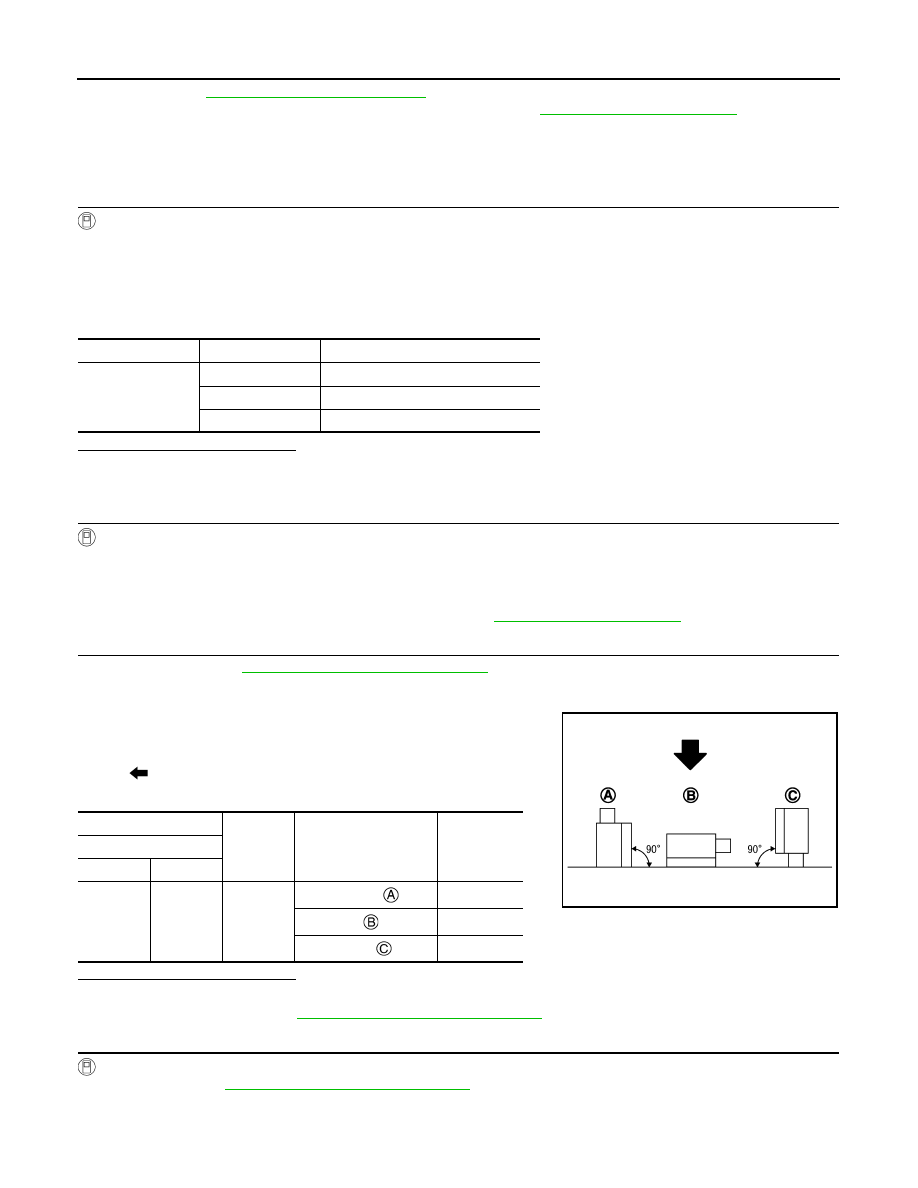
: Direction of gravitational force
+
−
Test condition
Voltage (Ap-
prox.)
TCM
Connector
Terminal
F119
14
Ground
Vertical (
−
1G)
1.17 V
Horizontal
2.5 V
Vertical (1G)
3.83 V
SCIA8343J