Nissan X-Trail 32. Manual - part 2136


  Главная      Nissan     Nissan X-Trail 32 - Service Manual


поиск по сайту            


содержание   ..  2134  2135  2136  2137   ..


Nissan X-Trail 32. Manual - part 2136


TM-502

< SYSTEM DESCRIPTION >

[CVT: RE0F10G]

SYSTEM

SELECT CONTROL

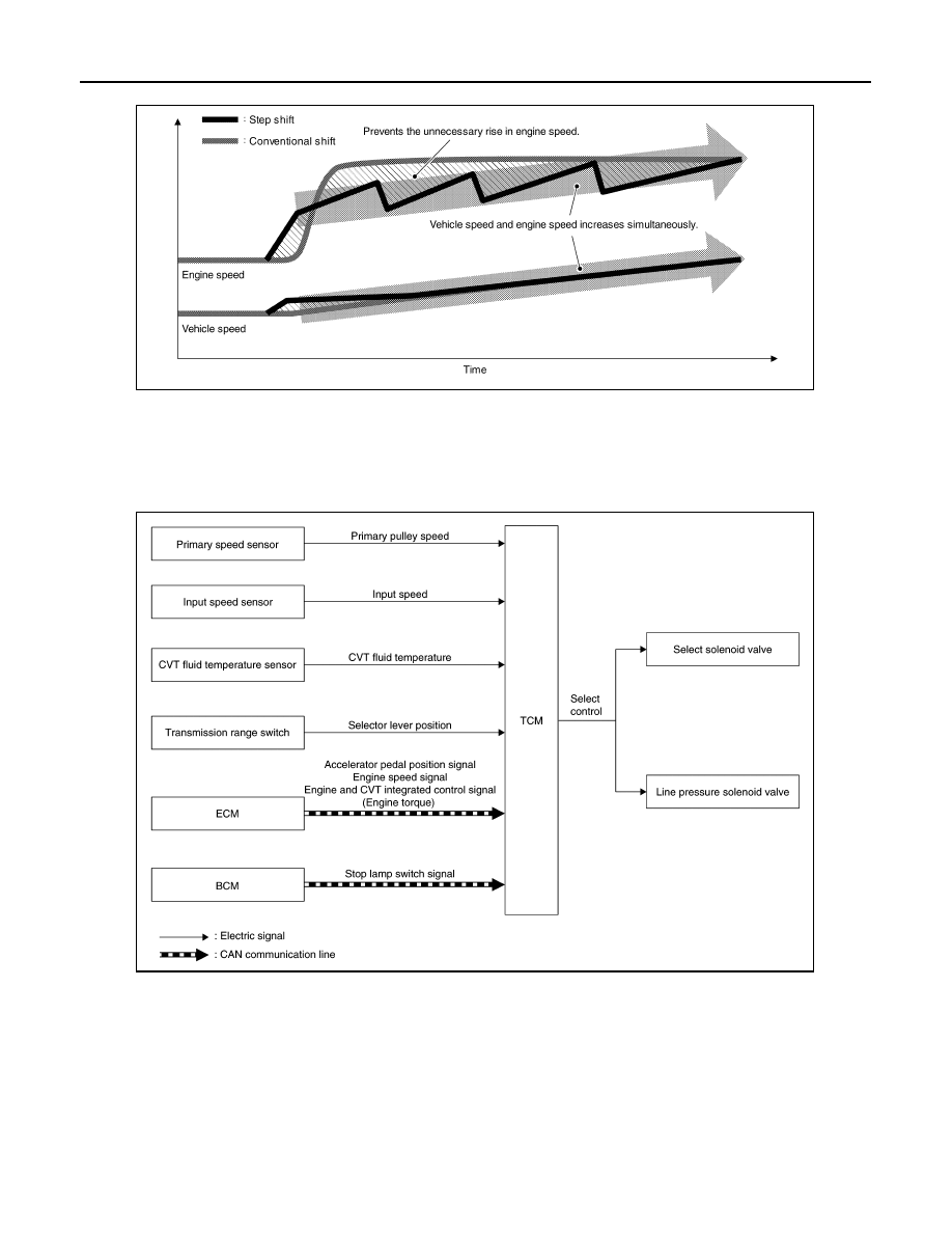
SELECT CONTROL : System Description

INFOID:0000000010622738

SYSTEM DIAGRAM

DESCRIPTION

Based on accelerator pedal angle, engine speed, primary pulley speed, and the input speed, the optimum
operating pressure is set to reduce impact of a selector lever operation while shifting from “N” (“P”) to “D” (“R”)
position.

LOCK-UP CONTROL

JSDIA5273GB

JSDIA3711GB

SYSTEM

TM-503

< SYSTEM DESCRIPTION >

[CVT: RE0F10G]

C

E

F

G

H

I

J

K

L

M

A

B

TM

N

O

P

LOCK-UP CONTROL : System Description

INFOID:0000000010622739

SYSTEM DIAGRAM

DESCRIPTION

• Controls for improvement of the transmission efficiency by engaging the torque converter clutch in the

torque converter and eliminating slip of the converter. Achieves comfortable driving with slip control of the
torque converter clutch. 

• The oil pressure feed circuit for the torque converter clutch piston chamber is connected to the torque con-

verter clutch control valve. The torque converter clutch control valve is switched by the torque converter
clutch solenoid valve with the signal from TCM. This controls the oil pressure circuit, which is supplied to the
torque converter clutch piston chamber, to the release side or engagement side. 

• If the CVT fluid temperature is low or the vehicle is in fail-safe mode due to malfunction, lock-up control is

prohibited. 

Lock-up engagement 

In lock-up engagement, the torque converter clutch solenoid valve makes the torque converter clutch control
valve locked up to generate the lock-up apply pressure. This pushes the torque converter clutch piston for
engagement. 

Lock-up release condition 

In lock-up release, the torque converter clutch solenoid valve makes the torque converter clutch control valve
non-locked up to drain the lock-up apply pressure. This does not engage the torque converter clutch piston. 

ECO MODE SYSTEM

ECO MODE SYSTEM : System Description

INFOID:0000000010622740

• Driving mode that selects the shift schedule with priority on fuel economy which gives low engine revolution.
• For details on ECO mode control, refer to 

DMS-7, "ECO MODE CONTROL : System Description"

.

• The gear shift line is not changed with the control mode change for the following conditions:
- When the selector lever is in “M” position.

FAIL-SAFE

JSDIA5314GB

TM-504

< SYSTEM DESCRIPTION >

[CVT: RE0F10G]

SYSTEM

If a malfunction occurs in the system of CVT during ECO mode, the ECO mode indicator turns OFF and the
control switches to the normal mode control.

STOP/START SYSTEM

STOP/START SYSTEM : System Description

INFOID:0000000010632035

• In the stop/start system, ECM performs integrated control based on the information from control units, sen-

sors and switches. For information, refer to 

EC-856, "STOP/START SYSTEM : System Description (CVT

models)"

.

• stop/start system operation OK is evaluated based on signals from sensors and switches.
• When stop/start system operation OK is determined, stop/start enable OK signal is sent to ECM through

CAN communication.

• stop/start readiness signal is received from ECM through CAN communication and the electric oil pump is

driven based on the signal.

• The electric oil pump relay is turned ON to prepare operation of the electric oil pump.
• The electric oil pump is driven in duty control.

STOP/START OPERATION PERMISSION CONDITION EVALUATED BY TCM

When TCM detects the vehicle status and stop/start system operation OK is determined, stop/start enable sig-
nal is sent to ECM through CAN communication.

TCM INDICATION CHARACTERISTICS

Item

Description

 Permission conditions

Transmission range switch

Selector lever position

Other than “R” position

G sensor

Gradient

±

14%

CVT fluid temperature sensor

CVT fluid temperature

25 – 110

°

C

Electric oil pump

Malfunction

Normal

Interval time

5 seconds or more from cancellation of previous stop/
start system operation

Secondary pressure

Control oil pressure

0.03 MPa or more

TCM indication signal (Duty)

Condition

0 – 5%

Disconnection or battery short-circuit

5 – 15%

Indicating stop of electric oil pump

15 – 85%

Indicating operation of electric oil pump

85 – 95%

Indicating operation of electric oil pump (Maximum power)

95 – 100%

Short to ground

SYSTEM

TM-505

< SYSTEM DESCRIPTION >

[CVT: RE0F10G]

C

E

F

G

H

I

J

K

L

M

A

B

TM

N

O

P

TIME CHART

INFORMATION DISPLAY (COMBINATION METER)

INFORMATION DISPLAY (COMBINATION METER) : Shift Position Indicator

INFOID:0000000010622741

PURPOSE

The shift position indicator displays the shift position of transmission.

JSDIA5443GB


содержание   ..  2134  2135  2136  2137   ..