Nissan X-Trail 32. Manual - part 2060


  Главная      Nissan     Nissan X-Trail 32 - Service Manual


поиск по сайту            


содержание   ..  2058  2059  2060  2061   ..


Nissan X-Trail 32. Manual - part 2060


TM-198

< UNIT DISASSEMBLY AND ASSEMBLY >

[6MT: RS6F52A]

MAINSHAFT AND GEAR

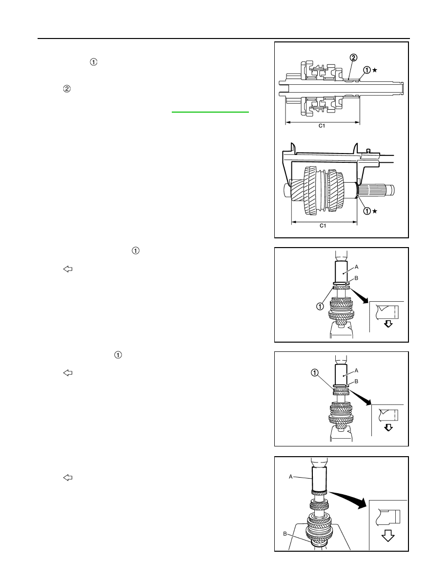
11. Select 4th main gear adjusting shim so that dimension (C1) sat-

isfies the standard value below and install 4th main gear adjust-
ing shim 

 onto mainshaft. For selecting 4th main gear

adjusting shim, refer to the latest parts information.

CAUTION:

Only one adjusting shim can be selected.

12. Press-fit 4th main gear 

 using the drifts (A and B).

CAUTION:

• Be careful with the orientation of 4th main gear.
• Never reuse 4th main gear.

13. Press-fit 5th main 

 gear using the drifts (A and B).

CAUTION:

• Be careful with the orientation of 5th main gear.
• Never reuse 5th main gear.

14. Install 5th-6th mainshaft spacer.

15. Press-fit 6th main gear using the drifts (A and B).

CAUTION:

• Be careful with the orientation of 6th main gear.
• Never reuse 6th main gear.

: 3rd-4th mainshaft spacer

 Dimension (C1)

: Refer to 

TM-225, "Dimension"

.

JPDIC0359ZZ

: Transaxle front side

A

: Drift (SST: ST33200000)

B

: Drift (SST: ST30901000)

JSDIA6506ZZ

: Transaxle front side

A

: Drift (SST: ST33200000)

B

: Drift (SST: ST30901000)

JSDIA6507ZZ

: Transaxle front side

A

: Drift (SST: ST33200000)

B

: Drift (SST: ST30901000)

JPDIC0372ZZ

MAINSHAFT AND GEAR

TM-199

< UNIT DISASSEMBLY AND ASSEMBLY >

[6MT: RS6F52A]

C

E

F

G

H

I

J

K

L

M

A

B

TM

N

O

P

16. Select 6th main gear adjusting shim and then install it onto mainshaft.

• Calculate thickness (S) of 6th main gear adjusting shim, as per

the following procedure so that end play dimension between
6th main gear and mainshaft rear bearing becomes the dimen-
sion shown below. For selecting 6th main gear adjusting shim,
refer to the latest parts information.

CAUTION:

Only one adjusting shim can be selected.

a.

Measure dimension (S

1

) and (S

2

) using a height gauge and a

pick tester.

b.

Install selected 6th main gear adjusting shim to mainshaft.

17. Press-fit mainshaft rear bearing using the drifts (A and B).

18. Install mainshaft C-rings onto mainshaft and check that end play

of mainshaft rear bearing satisfies the standard value.

• If measurement is outside the standard range, reselect main-

shaft C-rings. For selecting mainshaft C-ring, refer to the latest
parts information.

End play

Refer to 

TM-224, "End Play"

.

Dimension (S) = [(S

1

 (S

2

)] 

 End play

S

: Thickness of adjusting shim

S

1

: Dimension from mainshaft standard face to 
mainshaft rear bearing press-fit end face

S

2

: Dimension from mainshaft standard face to 
6th main gear end face

A

: Height gauge

B

: Pick tester

JPDIC0373ZZ

A

: Drift (SST: ST30720000)

B

: Drift (SST: ST30901000)

JSDIA6508ZZ

End play

: Refer to 

TM-224, "End Play"

.

SCIA0979E

TM-200

< UNIT DISASSEMBLY AND ASSEMBLY >

[6MT: RS6F52A]

MAINSHAFT AND GEAR

19. Install C-ring holder 

 and then install snap ring 

.

20. Check end play of 1st and 2nd main gears.

Inspection

INFOID:0000000010919417

MAINSHAFT AND GEAR

Check items below. If necessary, replace them with new ones.
• Damage, peeling, dent, uneven wear, bending, etc. of shaft.
• Excessive wear, damage, peeling, etc. of gears.
• Excessive wear, damage, peeling, etc. of cam side of clutch gears.

SYNCHRONIZER

Synchronizer Hub and Coupling Sleeve

Check items below. If necessary, replace them with new ones.
• Damage and excessive wear of contact surfaces of coupling

sleeve, synchronizer hub and shifting insert.

• Coupling sleeve and synchronizer hub must move smoothly.

Baulk Ring and Spread Spring

JPDIC0371ZZ

End play

: Refer to 

TM-224, "End Play"

.

SCIA0973E

JPDIC0143ZZ

SMT387A

MAINSHAFT AND GEAR

TM-201

< UNIT DISASSEMBLY AND ASSEMBLY >

[6MT: RS6F52A]

C

E

F

G

H

I

J

K

L

M

A

B

TM

N

O

P

Check damage or excessive wear on cam face of baulk ring or work-
ing face of insert. If necessary, replace it with new ones.

Baulk Ring Clearance for Triple Cone Synchronizer (1st and 2nd)

Check the clearance between outer baulk ring 

, synchronizer cone

, and inner baulk ring 

 as follows.

CAUTION:

The clearances (A), (B), and (C) are controlled with outer baulk
ring, synchronizer cone, and inner baulk ring as a set. Replace
them as a set if the clearances are outside the limit value.

1.

Measure the clearance (A) at 2 points or more diagonally oppo-
site using a feeler gauge (B) when pressing outer baulk ring 

,

synchronizer cone 

, and inner baulk ring 

 toward gear taper

cone 

. And then calculate mean value.

2.

Measure the clearance (B) at 2 points or more diagonally oppo-
site using a feeler gauge (A). And then calculate mean value.

SMT867D

JPDIC0308ZZ

Clearance (A)

: Refer to 

TM-224, "Baulk Ring Clear-

ance"

.

JPDIC0034ZZ

: Outer baulk ring

: Synchronizer cone

Clearance (B)

: Refer to 

TM-224, "Baulk Ring Clear-

ance"

.

JPDIC0307ZZ


содержание   ..  2058  2059  2060  2061   ..