содержание .. 1984 1985 1986 1987 ..
Nissan X-Trail 32. Manual - part 1986
ST-22
< REMOVAL AND INSTALLATION >
STEERING GEAR AND LINKAGE
CAUTION:
• Apply Molywhite LSG (manufactured by Kyodo yushi) to steering rack of proper quantity, if the
grease of steering rack adheres into boot inside in removing boots and the grease is removed.
• Never apply the grease to the surface between steering rack and inner socket screw part.
Removal and Installation
INFOID:0000000010839343
REMOVAL
1.
Set vehicle to the straight-ahead position.
2.
Remove hole cover.
3.
Remove steering shaft mounting bolt (steering gear side). Refer to
ST-17, "Removal and Installation"
4.
Separate steering shaft from steering gear assembly. Refer to
ST-17, "Removal and Installation"
CAUTION:
• Spiral cable may be cut if steering wheel turns while separating steering shaft and steering gear
assembly. Be sure to secure steering wheel using string to avoid turning.
• When removing steering shaft, never insert a tool, such as a screwdriver, into the yoke groove to
pull out the upper joint. In case of the violation of the above, replace steering shaft with a new
one.
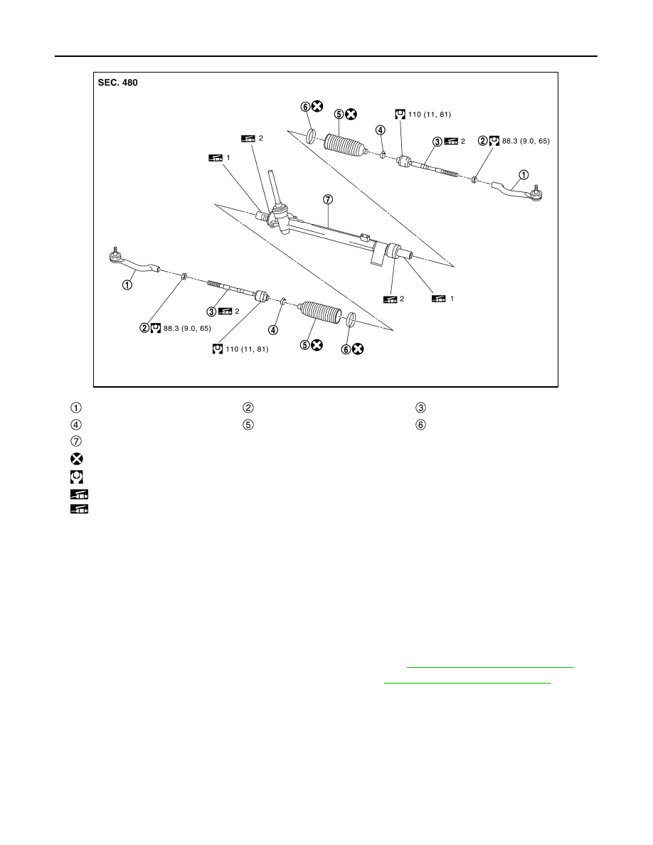
Outer socket
Outer socket lock nut
Inner socket
Boot clamp (small diameter)
Boot
Boot clamp (large diameter)
Gear housing assembly
: Always replace after every disassembly.
: N·m (kg-m, ft-lb)
1: Apply Molywhite LSG or equivalent.
2: Apply RENOLIT JP1619
JSGIA1451GB