содержание .. 1947 1948 1949 1950 ..
Nissan X-Trail 32. Manual - part 1949
SR-10
< SYSTEM DESCRIPTION >
COMPONENT PARTS
INFLATOR : Side air bag inflator
INFOID:0000000010927713
• Side air bag inflator
mainly consists of electric ignition device
(squib), heating agent, compressed gas, filter, and diffuser. These
items are stored in a cylinder-type container.
• In a lateral collision which exceeds the specified limit of the vehi-
cle, electric ignition device (squib) ignites igniting agent. Gas gen-
erating agent burns due to heat from igniting agent. Generated gas
(high temperature) inflates air bag through filter.
NOTE:
Filter removes and cools residues of gas generating agent.
INFLATOR : Curtain air bag inflator
INFOID:0000000010927714
• Curtain air bag inflator
mainly consists of electric ignition device
(squib), heating agent, compressed gas, and diffuser. These items
are stored in a cylinder-type container.
• In a lateral collision which exceeds the specified limit of the vehi-
cle, electric ignition device (squib) ignites igniting agent. Gas gen-
erating agent burns due to heat from igniting agent. Generated gas
(high temperature) inflates air bag
through filter.
NOTE:
Filter removes and cools residues of gas generating agent.
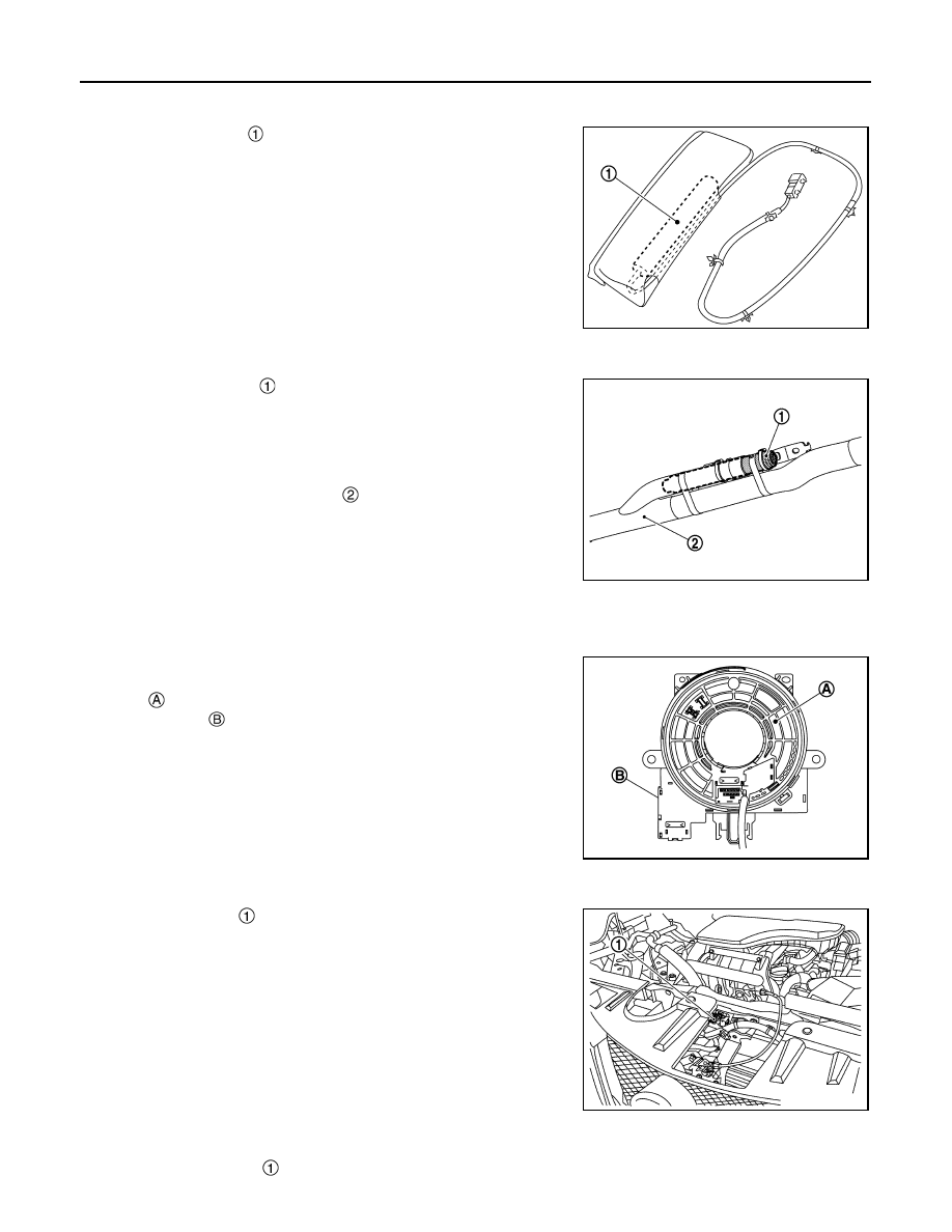
MAIN COMPONENT PARTS AND FUNCTIONS
MAIN COMPONENT PARTS AND FUNCTIONS : Spiral cable
INFOID:0000000010927715
• Spiral cable electrically connects air bag diagnosis sensor unit and
driver air bag module. Spiral cable mainly consists of the rotating
portion
which performs the same movement as steering wheel,
the fixed case
which is installed on steering wheel, and the
cable which connects the rotating portion.
• Spiral cable is built into steering angle sensor which is installed to
a space between combination switch and steering wheel.
MAIN COMPONENT PARTS AND FUNCTIONS : Crash zone sensor
INFOID:0000000010927716
• Crush zone sensor
is installed to charge port lid hinge assem-
bly. Crash zone sensor integrates frontal collision “G” sensor which
detects frontal collision impact that exceeds the specified limit of
the vehicle.
• In a frontal collision that exceeds the specified limit of the vehicle,
crush zone sensor detects impact. If frontal collision safing sensor
in air bag diagnosis sensor unit judges that impact is due to a colli-
sion, driver air bag, passenger air bag and seat belt pre-tensioner
(front and rear) operate.
MAIN COMPONENT PARTS AND FUNCTIONS : Satellite sensor
INFOID:0000000010927717
• B-pillar satellite sensor
in installed to center pillar lower portion of front seat belt retractor front side.
JMHIA1600ZZ
JMHIA2869ZZ
JMHIA2870ZZ
JMHIA2871ZZ