содержание .. 186 187 188 189 ..
Nissan X-Trail 32. Manual - part 188
BRC-218
< REMOVAL AND INSTALLATION >
[WITH VDC (ESP)]
ABS ACTUATOR AND ELECTRIC UNIT (CONTROL UNIT)
6.
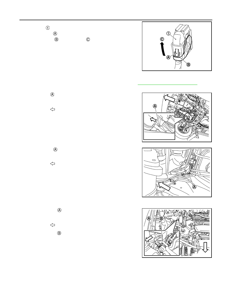
Disconnect ABS actuator and electric unit (control unit) harness
connector
, follow the procedure below.
a.
Push the pawl
.
b.
Move the lever
in the direction
until locked.
c.
Disconnect ABS actuator and electric unit (control unit) harness
connector.
7.
Loosen flare nut of brake tube using a flare nut wrench, and then remove brake tube between master cyl-
inder and ABS actuator and electric unit (control unit). Refer to
BR-32, "Removal and Installation"
.
8.
LIft up the vehicle.
9.
Remove clip
at the heat insulator lower side to make working
space.
10. Remove bolts
at the ABS actuator and electric unit (control
unit) bracket lower side.
11. Lift down the vehicle.
12. Remove the clip
of the air compressor high-pressure pipe to
make working space.
13. Remove the bolt
at the ABS actuator and electric unit (control
unit) bracket upper side, then remove the ABS actuator and
electric unit as a set with bracket.
CAUTION:
• Never remove and never install ABS actuator and electric
unit (control unit) by holding harness connector.
• Be careful not to drop ABS actuator and electric unit (con-
trol unit) and apply excessive impact to it.
14. Remove bracket from ABS actuator and electric unit (control unit).
INSTALLATION
Note the following, and install in the reverse order of removal.
JSFIA1350ZZ
: Vehicle front
JSFIA2488ZZ
: Vehicle front
JSFIA2489ZZ
: Vehicle front
JSFIA2490ZZ