содержание .. 1853 1854 1855 1856 ..
Nissan X-Trail 32. Manual - part 1855
POWER SUPPLY AND GROUND CIRCUIT
SEC-187
< DTC/CIRCUIT DIAGNOSIS >
[WITH INTELLIGENT KEY SYSTEM]
C
D
E
F
G
H
I
J
L
M
A
B
SEC
N
O
P
POWER SUPPLY AND GROUND CIRCUIT
SIREN CONTROL UNIT
SIREN CONTROL UNIT : Diagnosis Procedure
INFOID:0000000010994658
1.
CHECK FUSE
Check that the following fuse is not blown.
Is the fuse fusing?
YES
>> Replace the blown fuse after repairing the affected circuit if a fuse is blown.
NO
>> GO TO 2.
2.
CHECK POWER SUPPLY CIRCUIT
1.
Turn ignition switch OFF.
2.
Disconnect siren control unit connector.
3.
Check voltage between siren control unit harness connector and the ground.
Is the inspection result normal?
YES
>> GO TO 3.
NO
>> Repair or replace harness.
3.
CHECK GROUND CIRCUIT
Check continuity between siren control unit harness connectors and the ground.
Is the inspection result normal?
YES
>> INSPECTION END
NO
>> Repair or replace harness.
STEERING LOCK UNIT
STEERING LOCK UNIT : Diagnosis Procedure
INFOID:0000000010922233
1.
CHECK FUSE
Check that the following fuse is not blown.
Is the fuse blown?
YES
>> Replace the blown fuse after repairing the affected circuit if a fuse is blown.
NO
>> GO TO 2.
2.
CHECK STEERING LOCK UNIT POWER SUPPLY CIRCUIT1
1.
Turn ignition switch OFF.
2.
Disconnect steering lock unit connectors.
3.
Check voltage between harness steering lock unit connector and ground.
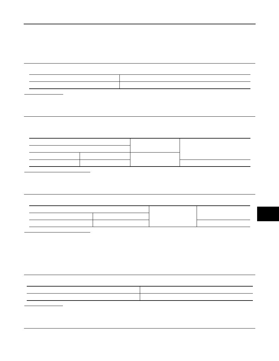
Signal name
Fuse
Battery power supply
14 (5 A)
(+)
(
−
)
Voltage
(Approx.)
Siren control unit
Connector
Terminal
Ground
B127
2
Battery voltage
Siren control unit
Ground
Continuity
Connector
Terminal
B127
5
Existed
Signal name
Fuse No.
Ignition ON signal
85 (5 A)