содержание .. 1736 1737 1738 1739 ..
Nissan X-Trail 32. Manual - part 1738
PWC-54
< DTC/CIRCUIT DIAGNOSIS >
POWER WINDOW MOTOR
2.
Disconnect rear power window switch LH connector.
3.
Check continuity between rear power window switch LH harness connector and rear power window motor
LH harness connector.
4.
Check continuity between rear power window switch LH connector and ground.
Is the inspection result normal?
YES
>> Replace rear power window switch LH. Refer to
PWC-75, "Removal and Installation"
.
NO
>> Repair or replace harness.
REAR RH
REAR RH : Component Function Check
INFOID:0000000010735237
1.
CHECK FUNCTION
Check rear power window motor RH operation with power window main switch (rear RH switch) or rear power
window switch RH.
Is the inspection result normal?
YES
>> INSPECTION END
NO
>> Refer to
PWC-54, "REAR RH : Diagnosis Procedure"
.
REAR RH : Diagnosis Procedure
INFOID:0000000010735238
LHD MODELS
1.
CHECK REAR POWER WINDOW MOTOR RH INPUT SIGNAL
1.
Turn ignition switch OFF.
2.
Disconnect rear power window motor RH connector.
3.
Turn ignition switch ON.
4.
Check voltage between rear power window motor RH harness connector and ground.
Is the inspection result normal?
YES
>> Replace rear power window motor RH. Refer to
GW-57, "Removal and Installation"
.
NO
>> GO TO 2.
2.
CHECK REAR POWER WINDOW MOTOR RH CIRCUIT
1.
Turn ignition switch OFF.
2.
Disconnect rear power window switch RH connector.
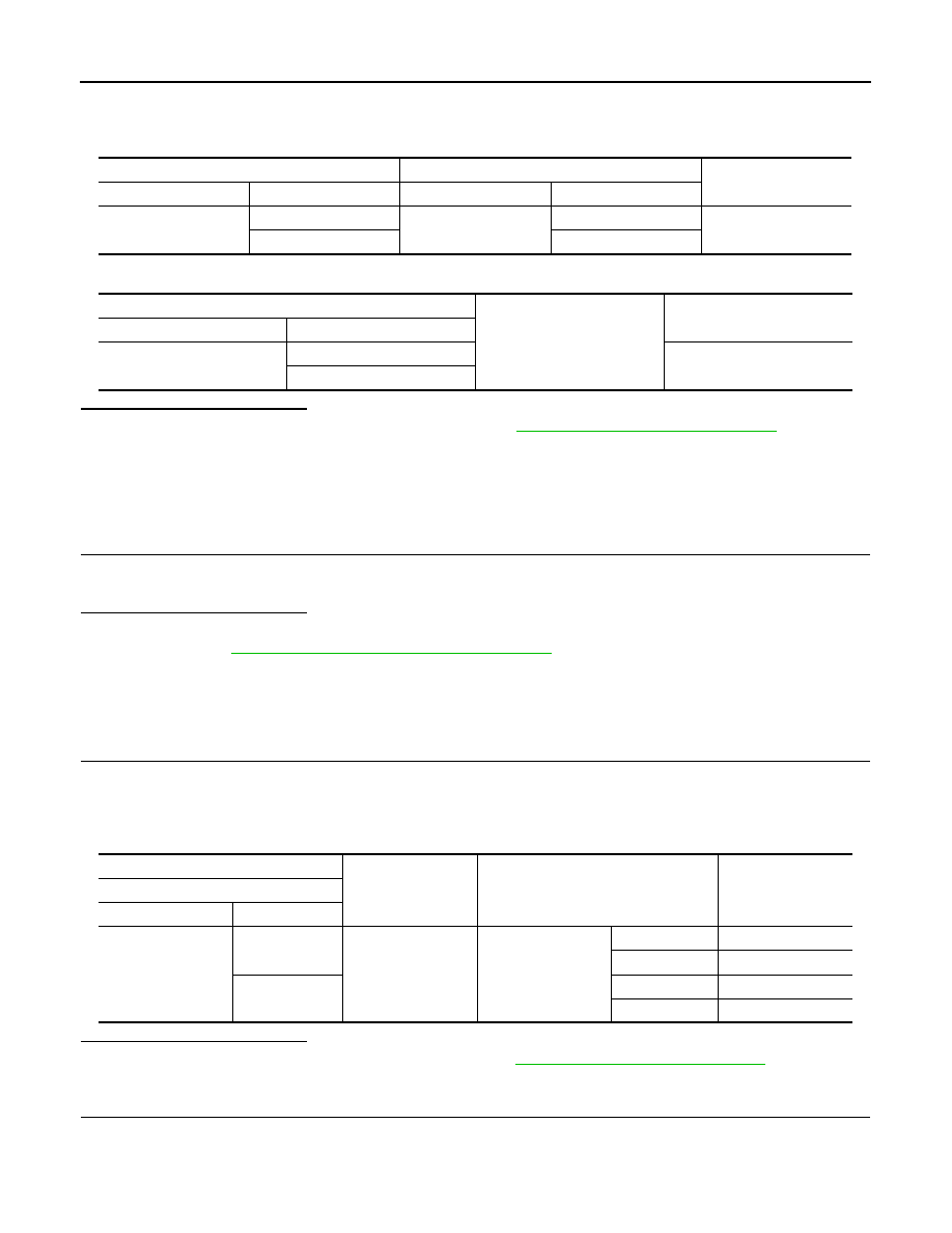
Rear power window switch LH
Rear power window motor LH
Continuity
Connector
Terminal
Connector
Terminal
D113
4
D112
3
Existed
5
1
Rear power window switch LH
Ground
Continuity
Connector
Terminal
D113
4
Not existed
5
(+)
(
−
)
Condition
Voltage
Rear power window motor RH
Connector
Terminal
D102
1
Ground
Rear power window
switch RH
UP
9 – 16 V
DOWN
0 – 1 V
3
UP
0 – 1 V
DOWN
9 – 16 V