содержание .. 1722 1723 1724 1725 ..
Nissan X-Trail 32. Manual - part 1724
PG-150
< REMOVAL AND INSTALLATION >
BATTERY TERMINAL WITH FUSIBLE LINK
BATTERY TERMINAL WITH FUSIBLE LINK
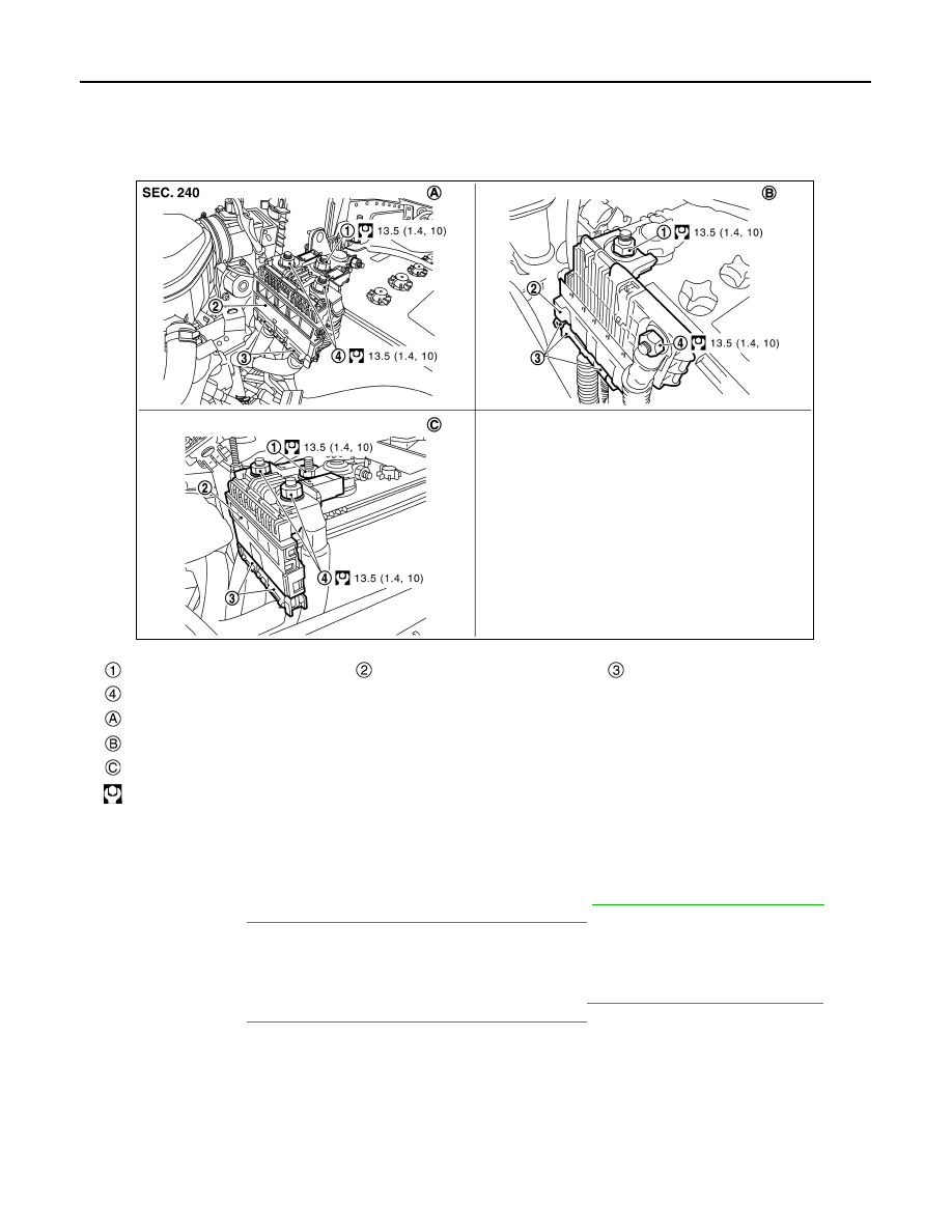
Exploded View
INFOID:0000000010709240
Removal and Installation
INFOID:0000000010709241
REMOVAL
1.
Disconnect the battery cable from the negative terminal. Refer to :
engine models) or
PG-140, "EXCEPT FOR R9M : Exploded View"
(except for R9M engine models).
CAUTION:
To prevent damage to the parts, disconnect the battery cable from the negative terminal first.
2.
Remove cover of battery positive terminal.
3.
Disconnect the battery cable from the positive terminal. Refer to
engine models) or
PG-140, "EXCEPT FOR R9M : Exploded View"
(except for R9M engine models).
4.
Remove harness mounting nut and battery terminal with fusible link mounting nut.
5.
Disconnect harness connector and remove battery terminal with fusible link.
INSTALLATION
Install in the reverse order of removal.
CAUTION:
To prevent damage to the parts, connect the battery cable to the positive terminal first.
: Fusible link holder mounting nut
: Battery terminal with fusible link
: Harness connector
: Harness mounting nut
: MR20DD engine models
: QR25DE engine models
: R9M engine models
: N·m (kg-m, ft-lb)
JSMIA1789GB