содержание .. 166 167 168 169 ..
Nissan X-Trail 32. Manual - part 168
BRC-138
< DTC/CIRCUIT DIAGNOSIS >
[WITH VDC (ESP)]
C1120, C1122, C1124, C1126 ABS IN VALVE SYSTEM
Is the inspection result normal?
YES
>> GO TO 3.
NO
>> Repair or replace error-detected parts, securely lock the connector, and GO TO 2.
2.
PERFORM SELF-DIAGNOSIS
Perform self-diagnosis for “ABS” again.
Is any DTC “C1120”, “C1122”, “C1124”, “C1126” detected?
YES
>> GO TO 3.
NO
>> INSPECTION END
3.
CHECK ABS IN VALVE POWER SUPPLY
1.
Turn the ignition switch OFF.
2.
Disconnect the ABS actuator and electric unit (control unit) harness connector.
3.
Check the voltage between ABS actuator and electric unit (control unit) harness connector and ground.
4.
Turn the ignition switch ON.
CAUTION:
Never start engine.
5.
Check the voltage between ABS actuator and electric unit (control unit) harness connector and ground.
Is the inspection result normal?
YES
>> GO TO 5.
NO
>> GO TO 4.
4.
CHECK ABS IN VALVE POWER SUPPLY CIRCUIT
1.
Turn the ignition switch OFF.
2.
Check the 30A fusible link (#G).
3.
Check the continuity and short circuit between ABS actuator and electric unit (control unit) harness con-
nector terminal (25) and 30A fusible link (#G).
Is the inspection result normal?
YES
>> Perform trouble diagnosis for battery power supply.
NO
>> Repair or replace error-detected parts.
5.
CHECK ABS IN VALVE GROUND CIRCUIT
1.
Turn the ignition switch OFF.
2.
Check the continuity between ABS actuator and electric unit (control unit) harness connector and the
ground.
Is the inspection result normal?
YES
>> GO TO 6.
NO
>> Repair or replace error-detected parts.
6.
CHECK TERMINAL
Check ABS actuator and electric unit (control unit) pin terminals for damage or loose connection with harness.
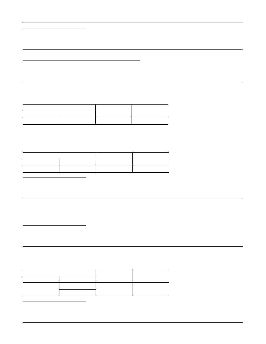
ABS actuator and electric unit (control unit)
—
Voltage
Connector
Terminal
E36
25
Ground
10 – 16 V
ABS actuator and electric unit (control unit)
—
Voltage
Connector
Terminal
E36
25
Ground
10 – 16 V
ABS actuator and electric unit (control unit)
—
Continuity
Connector
Terminal
E36
13
Ground
Existed
38