содержание .. 162 163 164 165 ..
Nissan X-Trail 32. Manual - part 164
BRC-122
< DTC/CIRCUIT DIAGNOSIS >
[WITH VDC (ESP)]
C1110, C1153 ABS ACTUATOR AND ELECTRIC UNIT (CONTROL UNIT)
C1110, C1153 ABS ACTUATOR AND ELECTRIC UNIT (CONTROL UNIT)
DTC Description
INFOID:0000000010723669
DTC DETECTION LOGIC
POSSIBLE CAUSE
• ABS actuator and electric unit (control unit)
FAIL-SAFE
The following functions are suspended.
• VDC function
• TCS function
• ABS function
• EBD function (When DTC “C1110”)
• Brake limited slip differential (BLSD) function
• Brake assist function
• hill start assist function
• Brake force distribution function
• Advanced hill descent control function (4WD models with gasoline engine)
• Active trace control function (control of chassis control module)
• Active ride control function (control of chassis control module)
DTC CONFIRMATION PROCEDURE
1.
PRECONDITIONING
If “DTC CONFIRMATION PROCEDURE” has been previously conducted, always turn the ignition switch OFF
and wait at least 10 seconds before conducting the next test.
>> GO TO 2.
2.
CHECK DTC DETECTION
With CONSULT
1.
Turn the ignition switch OFF to ON.
2.
Perform self-diagnosis for “ABS”.
Is any DTC “C1110” or “C1153” detected?
YES
>> Proceed to
BRC-122, "Diagnosis Procedure"
NO-1
>> To check malfunction symptom before repair: Refer to
GI-44, "Intermittent Incident"
.
NO-2
>> Confirmation after repair: INSPECTION END
Diagnosis Procedure
INFOID:0000000010723670
1.
CHECK SELF-DIAGNOSIS RESULTS
Replace the ABS actuator and electric unit (control unit) even if other display than “C1110” or “C1153” is dis-
played in self-diagnosis for “ABS”.
>>
Replace the ABS actuator and electric unit (control unit).
• LHD models: Refer to
BRC-217, "LHD : Removal and Installation"
• RHD models: Refer to
BRC-220, "RHD : Removal and Installation"
.
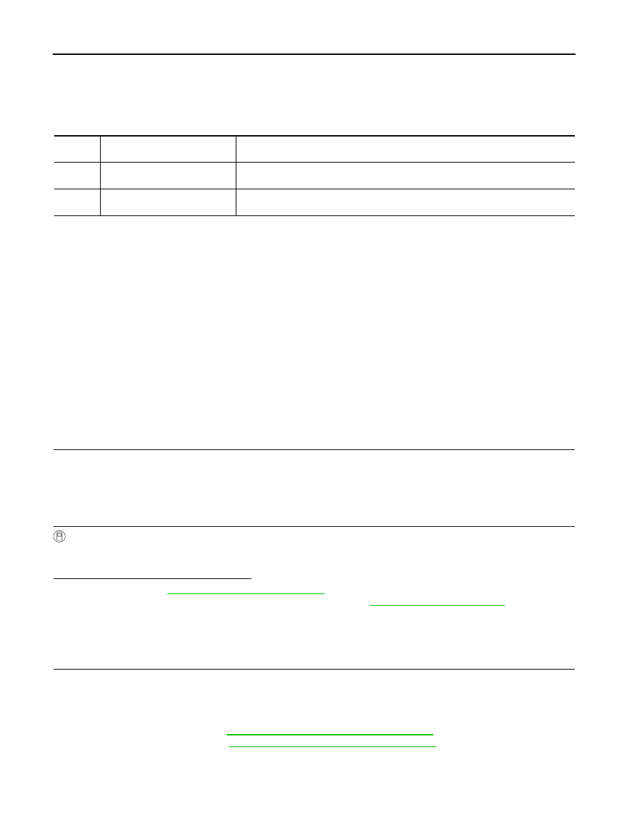
DTC
Display Item
(Trouble diagnosis content)
Malfunction detected condition
C1110
CONTROLLER FAILURE
(Controller failure)
When there is an internal malfunction in the ABS actuator and electric unit (control unit).
C1153
EMERGENCY BRAKE
(Emergency brake)
When ABS actuator and electric unit (control unit) is malfunctioning. (Pressure increase
is too much or too little)