Nissan X-Trail 32. Manual - part 1517


  Главная      Nissan     Nissan X-Trail 32 - Service Manual


поиск по сайту            


содержание   ..  1515  1516  1517  1518   ..


Nissan X-Trail 32. Manual - part 1517


LAN-108

< PRECAUTION >

[CAN GATEWAY]

PRECAUTIONS

PRECAUTION

PRECAUTIONS

Precaution for Supplemental Restraint System (SRS) "AIR BAG" and "SEAT BELT 
PRE-TENSIONER"

INFOID:0000000010715341

The Supplemental Restraint System such as “AIR BAG” and “SEAT BELT PRE-TENSIONER”, used along
with a front seat belt, helps to reduce the risk or severity of injury to the driver and front passenger for certain
types of collision. Information necessary to service the system safely is included in the SR and SB section of
this Service Manual.

WARNING:

• To avoid rendering the SRS inoperative, which could increase the risk of personal injury or death in

the event of a collision which would result in air bag inflation, all maintenance must be performed by
an authorized NISSAN/INFINITI dealer.

• Improper maintenance, including incorrect removal and installation of the SRS, can lead to personal

injury caused by unintentional activation of the system. For removal of Spiral Cable and Air Bag
Module, see the SR section.

• Do not use electrical test equipment on any circuit related to the SRS unless instructed to in this

Service Manual. SRS wiring harnesses can be identified by yellow and/or orange harnesses or har-
ness connectors.

PRECAUTIONS WHEN USING POWER TOOLS (AIR OR ELECTRIC) AND HAMMERS

WARNING:

• When working near the Airbag Diagnosis Sensor Unit or other Airbag System sensors with the Igni-

tion ON or engine running, DO NOT use air or electric power tools or strike near the sensor(s) with a
hammer. Heavy vibration could activate the sensor(s) and deploy the air bag(s), possibly causing
serious injury.

• When using air or electric power tools or hammers, always switch the Ignition OFF, disconnect the

battery and wait at least three minutes before performing any service.

Precautions for Removing Battery Terminal

INFOID:0000000011010967

• With the adoption of Auto ACC function, ACC power is automatically supplied by operating the intelligent key

or remote keyless entry or by opening/closing the driver side door. In addition, ACC power is supplied even
after the ignition switch is turned to the OFF position, i.e. ACC power is supplied for a certain fixed time.

• When disconnecting the 12V battery terminal, turn off the ACC

power before disconnecting the 12V battery terminal, observing
“How to disconnect 12V battery terminal” described below.
NOTE:
Some ECUs operate for a certain fixed time even after ignition
switch is turned OFF and ignition power supply is stopped. If the
battery terminal is disconnected before ECU stops, accidental DTC
detection or ECU data damage may occur.

•  For vehicles with the 2-batteries, be sure to connect the main bat-

tery and the sub battery before turning ON the ignition switch.
NOTE:
If the ignition switch is turned ON with any one of the terminals of
main battery and sub battery disconnected, then DTC may be detected.

•  After installing the 12V battery, always check "Self Diagnosis Result" of all ECUs and erase DTC.

NOTE:
The removal of 12V battery may cause a DTC detection error.

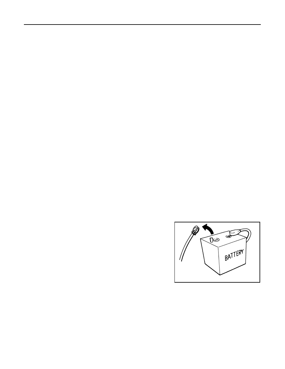
HOW TO DISCONNECT 12V BATTERY TERMINAL

Disconnect 12V battery terminal according to Instruction 1 or Instruction 2 described below.
For vehicles parked by ignition switch OFF, refer to Instruction 2.

INSTRUCTION 1

1.

Open the hood.

2.

Turn key switch to the OFF position with the driver side door opened.

3.

Get out of the vehicle and close the driver side door.

SEF289H

LAN

PRECAUTIONS

LAN-109

< PRECAUTION >

[CAN GATEWAY]

C

D

E

F

G

H

I

J

K

L

B

A

O

P

N

4.

Wait at least 3 minutes. For vehicle with the engine listed below, remove the battery terminal after a lapse
of the specified time.

CAUTION:

While waiting, never operate the vehicle such as locking, opening, and closing doors. Violation of
this caution results in the activation of ACC power supply according to the Auto ACC function.

5.

Remove 12V battery terminal.

CAUTION:

After installing 12V battery, always check self-diagnosis results of all ECUs and erase DTC.

INSTRUCTION 2 (FOR VEHICLES PARKED BY IGNITION SWITCH OFF)

1.

Unlock the door with intelligent key or remote keyless entry.
NOTE:
At this moment, ACC power is supplied.

2.

Open the driver side door.

3.

Open the hood.

4.

Close the driver side door.

5.

Wait at least 3 minutes.

CAUTION:

While waiting, never operate the vehicle such as locking, opening, and closing doors. Violation of
this caution results in the activation of ACC power supply according to the Auto ACC function.

6.

Remove 12V battery terminal.

CAUTION:

After installing 12V battery, always check self-diagnosis results of all ECUs and erase DTC.

D4D engine

: 20 minutes

HRA2DDT

: 12 minutes

K9K engine

: 4 minutes

M9R engine

: 4 minutes

R9M engine

: 4 minutes

V9X engine

: 4 minutes

LAN-110

< SYSTEM DESCRIPTION >

[CAN GATEWAY]

SYSTEM

SYSTEM DESCRIPTION

SYSTEM

System Description

INFOID:0000000010715343

SYSTEM DIAGRAM

SYSTEM DESCRIPTION

• The BCM has a CAN gateway function.
• The BCM communicates between two CAN communication circuits.
• The BCM selects and transmits only necessary information.

JSMIA1666GB

LAN

DIAGNOSIS SYSTEM (CAN GATEWAY)

LAN-111

< SYSTEM DESCRIPTION >

[CAN GATEWAY]

C

D

E

F

G

H

I

J

K

L

B

A

O

P

N

DIAGNOSIS SYSTEM (CAN GATEWAY)

CONSULT Function

INFOID:0000000010715344

APPLICATION ITEM

CONSULT performs the following functions via CAN communication with CAN gateway.

ECU IDENTIFICATION

The CAN gateway part number is displayed.

SELF DIAGNOSTIC RESULT

Refer to 

LAN-112, "DTC Index"

.

• When “CRNT” is displayed on self-diagnosis result
- The system is presently malfunctioning.
• When “PAST” is displayed on self-diagnosis result
- System malfunction in the past is detected, but the system is presently normal.

Freeze Frame Data (FFD)

When DTC is detected, a vehicle state shown below is recorded and displayed on CONSULT.

DATA MONITOR

CONFIGURATION

CAUTION:

Follow the instructions listed below. Failure to do this may cause malfunctions to the BCM.:
• When replacing BCM you must perform “Read / Write Configuration” or “Manual Configuration” with

CONSULT.

• Complete the procedure of “Read / Write Configuration” or “Manual Configuration” in order.
• If you set incorrect “Read / Write Configuration” or “Manual Configuration”, incidents might occur.
• Configuration is different for each vehicle model. Confirm configuration of each vehicle model.
• Never perform “Read / Write Configuration” or “Manual Configuration” except for new BCM. 

Diagnosis mode

Function Description

Ecu Identification

The CAN gateway software number is displayed.

Self Diagnostic Result

Displays the diagnosis results of BCM CAN gateway function.

Data Monitor

Displays real-time input/output data of BCM CAN gateway function.

Configuration

• Read and save the vehicle specification.
• Write the vehicle specification when replacing of BCM.

Item name

Display item

Milage
(Kirometers)

Displays the total mileage when a DTC is detected.

Monitor item

Description

CAN GW MODE
(UNCONF/MALF/NORMAL)

Displays the status of BCM CAN gateway function.

IGN SIGNAL
(Off/On)

Displays the status of ignition switch.

Function

Description

Read / Write Configuration

Before Replace ECU

• Reads the vehicle configuration of current BCM.
• Saves the read vehicle configuration.

After Replace ECU

Writes the vehicle configuration with saved data.

Manual Configuration

Writes the vehicle configuration with manual selection.


содержание   ..  1515  1516  1517  1518   ..