Nissan X-Trail 32. Manual - part 1516


  Главная      Nissan     Nissan X-Trail 32 - Service Manual


поиск по сайту            


содержание   ..  1514  1515  1516  1517   ..


Nissan X-Trail 32. Manual - part 1516


LAN-104

< DTC/CIRCUIT DIAGNOSIS >

[CAN]

CAN COMMUNICATION CIRCUIT 2

CAN COMMUNICATION CIRCUIT 2

Diagnosis Procedure

INFOID:0000000010715340

1.

CONNECTOR INSPECTION

1.

Turn the ignition switch OFF.

2.

Disconnect the battery cable from the negative terminal.

3.

Check the terminals and connectors of the BCM for damage, bend and loose connection (unit side and
connector side).

Is the inspection result normal?

YES

>> GO TO 2.

NO

>> Repair the terminal and connector.

2.

CHECK HARNESS CONTINUITY (OPEN CIRCUIT)

1.

Disconnect the connector of BCM.

2.

Check the continuity between the BCM harness connector terminals.

Is the inspection result normal?

YES

>> GO TO 3.

NO

>> Check the harness and repair or replace the root cause.

3.

CHECK HARNESS CONTINUITY (SHORT CIRCUIT)

1.

Disconnect all the unit connectors on CAN communication circuit 2.

2.

Check the continuity between the BCM harness connector terminals.

Is the inspection result normal?

YES

>> GO TO 4.

NO

>> Check the harness and repair or replace the root cause.

4.

CHECK HARNESS CONTINUITY (SHORT CIRCUIT)

Check the continuity between the BCM and the ground.

Is the inspection result normal?

YES

>> GO TO 5.

NO

>> Check the harness and repair or replace (if shield line is short) the root cause.

5.

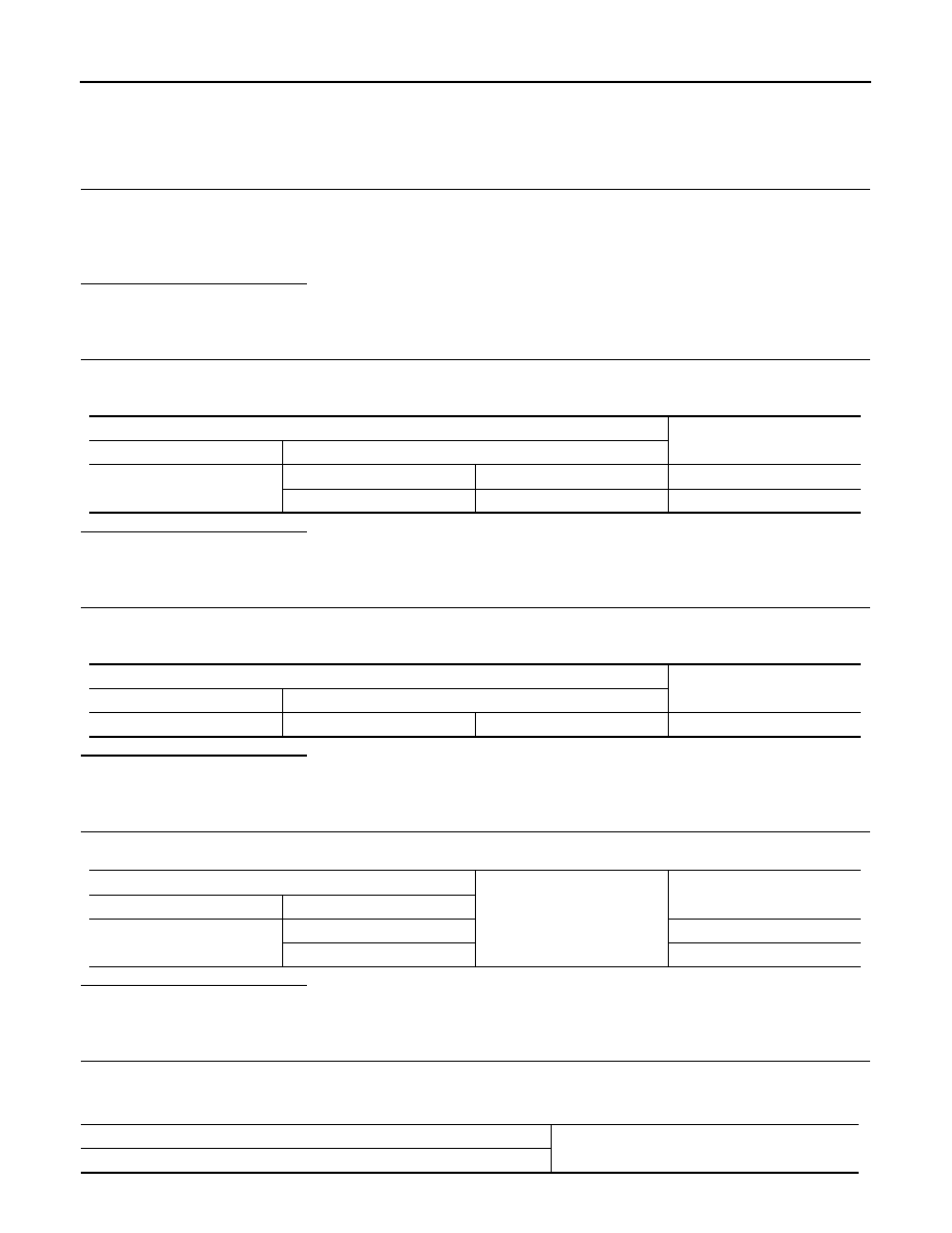
CHECK BCM TERMINATION CIRCUIT

1.

Remove the BCM.

2.

Check the resistance between the BCM terminals.

BCM harness connector

Continuity

Connector No.

Terminal No.

B87

46

48

Existed

45

49

Existed

BCM harness connector

Continuity

Connector No.

Terminal No.

B87

46

45

Not existed

BCM harness connector

Ground

Continuity

Connector No.

Terminal No.

B87

46

Not existed

45

Not existed

BCM

Resistance (

)

Terminal No.

LAN

CAN COMMUNICATION CIRCUIT 2

LAN-105

< DTC/CIRCUIT DIAGNOSIS >

[CAN]

C

D

E

F

G

H

I

J

K

L

B

A

O

P

N

Is the measurement value within the specification?

YES

>> GO TO 6.

NO

>> Replace the chassis control module.

6.

CHECK SYMPTOM

Connect all the connectors. Check if the symptoms described in the “Symptom (Results from interview with
customer)” are reproduced. 

Inspection result

Reproduced>>GO TO 7.
Non-reproduced>>Start the diagnosis again. Follow the trouble diagnosis procedure when past error is

detected.

7.

CHECK UNIT REPRODUCTION

Perform the reproduction test as per the following procedure for each unit.
1.

Turn the ignition switch OFF.

2.

Disconnect the battery cable from the negative terminal.

3.

Disconnect one of the unit connectors of CAN communication circuit 2.
NOTE:
BCM has two termination circuits. Check other units first.

4.

Connect the battery cable to the negative terminal. Check if the symptoms described in the “Symptom
(Results from interview with customer)” are reproduced. 
NOTE:
Although unit-related error symptoms occur, do not confuse them with other symptoms. 

Inspection result

Reproduced>>Connect the connector. Check other units as per the above procedure.
Non-reproduced>>Replace the unit whose connector was disconnected.

46

45

Approx. 108 – 132

48

49

Approx. 108 – 132

LAN-106

< DTC/CIRCUIT DIAGNOSIS >

[CAN]

CHASSIS COMMUNICATION CIRCUIT

CHASSIS COMMUNICATION CIRCUIT

Diagnosis Procedure

INFOID:0000000011009333

1.

CHECK CAN DIAGNOSIS

Check the CAN diagnosis results from CONSULT to see that the CAN communication circuit 1 and CAN com-
munication circuit 2 have no malfunction.

Are the CAN communication 1 and CAN communication 2 circuits normal?

YES

>> GO TO 2.

NO

>> Check and repair CAN communication circuit 1 and/or CAN communication circuit 2.

2.

CONNECTOR INSPECTION

1.

Turn the ignition switch OFF.

2.

Disconnect the battery cable from the negative terminal.

3.

Check the terminals and connectors of the chassis control module for damage, bend and loose connec-
tion (unit side and connector side).

Is the inspection result normal?

YES

>> GO TO 3.

NO

>> Repair the terminal and connector.

3.

CHECK HARNESS CONTINUITY (OPEN CIRCUIT)

1.

Disconnect the connector of chassis control module.

2.

Check the continuity between the chassis control module harness connector terminals.

Is the inspection result normal?

YES

>> GO TO 4.

NO

>> Check the harness and repair or replace the root cause.

4.

CHECK HARNESS CONTINUITY (SHORT CIRCUIT)

1.

Disconnect all the unit connectors on chassis communication circuit.

2.

Check the continuity between the chassis control module harness connector terminals.

Is the inspection result normal?

YES

>> GO TO 5.

NO

>> Check the harness and repair or replace the root cause.

5.

CHECK HARNESS CONTINUITY (SHORT CIRCUIT)

Check the continuity between the chassis control module and the ground.

Is the inspection result normal?

YES

>> GO TO 6.

NO

>> Check the harness and repair or replace (if shield line is short) the root cause.

Chassis control module harness connector

Continuity

Connector No.

Terminal No.

M73

11

19

Existed

8

7

Existed

Chassis control module harness connector

Continuity

Connector No.

Terminal No.

M73

11

8

Not existed

Chassis control module harness connector

Ground

Continuity

Connector No.

Terminal No.

M73

11

Not existed

8

Not existed

LAN

CHASSIS COMMUNICATION CIRCUIT

LAN-107

< DTC/CIRCUIT DIAGNOSIS >

[CAN]

C

D

E

F

G

H

I

J

K

L

B

A

O

P

N

6.

CHECK CHASSIS CONTROL MODULE TERMINATION CIRCUIT

1.

Remove the chassis control module.

2.

Check the resistance between the chassis control module terminals.

Is the measurement value within the specification?

YES

>> GO TO 7.

NO

>> Replace the chassis control module.

7.

CHECK SYMPTOM

Connect all the connectors. Check if the symptoms described in the “Symptom (Results from interview with
customer)” are reproduced. 

Inspection result

Reproduced>>GO TO 8.
Non-reproduced>>Start the diagnosis again. Follow the trouble diagnosis procedure when past error is

detected.

8.

CHECK UNIT REPRODUCTION

Perform the reproduction test as per the following procedure for each unit.
1.

Turn the ignition switch OFF.

2.

Disconnect the battery cable from the negative terminal.

3.

Disconnect one of the unit connectors of chassis communication circuit.
NOTE:
Chassis control module has two termination circuits. Check other units first.

4.

Connect the battery cable to the negative terminal. Check if the symptoms described in the “Symptom
(Results from interview with customer)” are reproduced. 
NOTE:
Although unit-related error symptoms occur, do not confuse them with other symptoms. 

Inspection result

Reproduced>>Connect the connector. Check other units as per the above procedure.
Non-reproduced>>Replace the unit whose connector was disconnected.

Chassis control module

Resistance (

)

Terminal No.

11

8

Approx. 108 – 132

19

7

Approx. 108 – 132


содержание   ..  1514  1515  1516  1517   ..