содержание .. 1441 1442 1443 1444 ..
Nissan X-Trail 32. Manual - part 1443
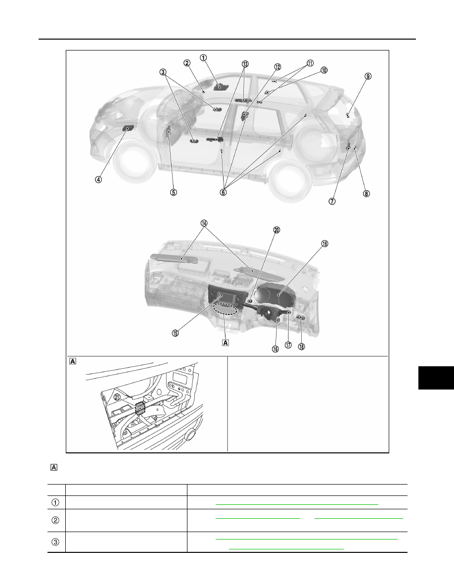
COMPONENT PARTS
INL-9
< SYSTEM DESCRIPTION >
C
D
E
F
G
H
I
J
K
M
A
B
INL
N
O
P
Behind A/C control
No.
Component
Function
Map lamp
INL-6, "Interior Lamp Appearance and Bulb Specifications"
Light & rain sensor*
1
Refer to
*
2
EXL-224, "Light & Rain Sensor"
*
3
.
Door lock and unlock switch
Refer to
DLK-31, "DOOR LOCK SYSTEM : Door Lock and Unlock Switch"
(Type 1*
4
) or
DLK-644, "Door Lock and Unlock Switch"
(Type 3*
5
).
JMLIA5541ZZ