Nissan X-Trail 32. Manual - part 1433


  Главная      Nissan     Nissan X-Trail 32 - Service Manual


поиск по сайту            


содержание   ..  1431  1432  1433  1434   ..


Nissan X-Trail 32. Manual - part 1433


BLOWER MOTOR

HAC-207

< DTC/CIRCUIT DIAGNOSIS >

[MANUAL AIR CONDITIONING]

C

D

E

F

G

H

J

K

L

M

A

B

HAC

N

O

P

10.

CHECK FAN CONTROL AMP.

Check fan control amp. Refer to 

HAC-208, "Component Inspection (Fan Control Amp.)"

.

Is the inspection result normal?

YES

>> Replace A/C amp. Refer to 

HAC-222, "Removal and Installation"

.

NO

>> Replace fan control amp. Refer to 

HAC-227, "Removal and Installation"

.

11.

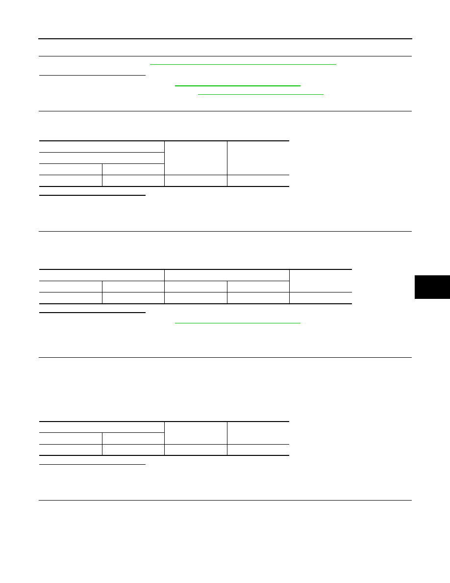
CHECK A/C AMP. IGNITION POWER SUPPLY FEEDBACK SIGNAL

1.

Turn ignition switch ON.

2.

Check voltage between A/C amp. harness connector and ground.

Is the inspection result normal?

YES

>> GO TO 12.

NO

>> Repair harness or connector between A/C amp. and fuse.

12.

CHECK BLOWER MOTOR FEEDBACK SIGNAL CIRCUIT FOR OPEN

1.

Turn ignition switch OFF.

2.

Disconnect blower motor connector and A/C amp. connector.

3.

Check continuity between blower motor harness connector and A/C amp. harness connector. 

Is the inspection result normal?

YES

>> Replace A/C amp. Refer to 

HAC-222, "Removal and Installation"

.

NO

>> Repair harness or connector.

13.

CHECK BLOWER MOTOR FEEDBACK SIGNAL CIRCUIT AND FAN CONTROL AMP. POWER SUPPLY

CIRCUIT FOR SHORT

1.

Turn ignition switch OFF.

2.

Disconnect following connectors.

-

Blower fan motor

-

Fan control amp.

-

A/C amp.

3.

Check continuity between blower motor harness connector and ground. 

Is the inspection result normal?

YES

>> GO TO 14.

NO

>> Repair harness or connector.

14.

CHECK FAN CONTROL AMP. CONTROL SIGNAL CIRCUIT FOR SHORT TO POWER SUPPLY

Check harness between fan control amp. harness connector and A/C amp. harness connector for short to
power supply. 

+

Voltage

A/C amp.

Connector

Terminal

M132

4

Ground

11 – 14 V

Blower motor

A/C amp.

Continuity

Connector

Terminal

Connector

Terminal

M347

2

M132

17

Existed

Blower motor

Continuity

Connector

Terminal

M347

2

Ground

Not existed

HAC-208

< DTC/CIRCUIT DIAGNOSIS >

[MANUAL AIR CONDITIONING]

BLOWER MOTOR

Is the inspection result normal?

YES

>> GO TO 10.

NO

>> Repair harness or connector.

Component Inspection (Blower Motor)

INFOID:0000000010939856

1.

CHECK BLOWER MOTOR-I

1.

Remove blower motor. Refer to 

VTL-15, "Removal and Installation"

.

2.

Check that there is not any mixing foreign object in the blower motor. 

Is the inspection result normal?

YES

>> GO TO 2.

NO

>> Replace blower motor. Refer to 

VTL-15, "Removal and Installation"

.

2.

CHECK BLOWER MOTOR-II

Check that there is not breakage or damage in the blower motor. 

Is the inspection result normal?

YES

>> GO TO 3.

NO

>> Replace blower motor. Refer to 

VTL-15, "Removal and Installation"

.

3.

CHECK BLOWER MOTOR-III

Check that blower motor turns smoothly. 

Is the inspection result normal?

YES

>> INSPECTION END

NO

>> Replace blower motor. Refer to 

VTL-15, "Removal and Installation"

.

Component Inspection (Blower Relay)

INFOID:0000000010939857

1.

CHECK BLOWER RELAY

1.

Remove blower relay. Refer to 

PG-84, "Fuse, Connector and Terminal Arrangement"

2.

Check continuity between blower relay terminal 3 and 5 when
the voltage is supplied between terminal 1 and 2. 

Is the inspection result normal?

YES

>> INSPECTION END

NO

>> Replace blower relay.

Component Inspection (Fan Control Amp.)

INFOID:0000000010939858

1.

CHECK FAN CONTROL AMP.

1.

Remove fan control amp. Refer to 

HAC-227, "Removal and Installation"

2.

Check continuity between fan control amp. terminals.

Fan control amp.

Voltage

Connector

Terminal

M346

2

Ground

0 V

Terminal

Voltage

Continuity

3

5

ON

Existed

OFF

Not existed

JSIIA1551ZZ

+

Continuity

Terminal

Terminal

1

3

Existed

3

1

Not existed

BLOWER MOTOR

HAC-209

< DTC/CIRCUIT DIAGNOSIS >

[MANUAL AIR CONDITIONING]

C

D

E

F

G

H

J

K

L

M

A

B

HAC

N

O

P

Is the inspection result normal?

YES

>> INSPECTION END

NO

>> Replace fan control amp. Refer to 

HAC-227, "Removal and Installation"

.

HAC-210

< DTC/CIRCUIT DIAGNOSIS >

[MANUAL AIR CONDITIONING]

MAGNET CLUTCH

MAGNET CLUTCH

Component Function Check

INFOID:0000000010939859

1.

CHECK MAGNET CLUTCH OPERATION

CONSULT ACTIVE TEST

1.

Select “COMPRESSOR” of IPDM E/R active test item.

2.

With operating the test item, check magnet clutch operation by listening and viewing.

Does it operate normally?

YES

>> INSPECTION END

NO

>> Refer to 

HAC-210, "Diagnosis Procedure"

.

Diagnosis Procedure

INFOID:0000000010939860

1.

CHECK MAGNET CLUTCH

CONSULT

1.

Turn ignition switch OFF

2.

Disconnect compressor connector. 

3.

Select “COMPRESSOR” of IPDM E/R active test item.

4.

With operating the test item, check voltage between compressor harness connector and ground.

Does it operate normally?

YES

>> GO TO 4.

NO

>> GO TO 2.

2.

CHECK FUSE

1.

Turn ignition switch OFF

2.

Check 15 A fuse (No. 87, located in IPDM E/R).
NOTE:
Refer to 

PG-89, "Fuse, Connector and Terminal Arrangement"

Is the inspection result normal?

YES

>> GO TO 3.

NO

>> Replace the blown fuse after repairing the affected circuit if a fuse is blown. 

3.

CHECK MAGNET CLUTCH POWER SUPPLY CIRCUIT FOR OPEN

1.

Disconnect IPDM E/R connector.

2.

Check continuity between IPDM E/R harness connector and compressor harness connector. 

Is the inspection result normal?

YES

>> Replace IPDM E/R. Refer to 

PCS-60, "Removal and Installation"

.

NO

>> Repair harness or connector. 

4.

CHECK MAGNET CLUTCH GROUND CIRCUIT FOR OPEN

Check continuity between compressor harness connector and ground. 

+

Condition

Voltage

Compressor

Connector

Terminal

F17

1

Ground

Active test: COM-
PRESSOR

Off

0 - 1 V

On

9 - 16 V

IPDM E/R

Compressor

Continuity

Connector

Terminal

Connector

Terminal

F72

65

F17

1

Existed


содержание   ..  1431  1432  1433  1434   ..