Nissan X-Trail 32. Manual - part 1423


  Главная      Nissan     Nissan X-Trail 32 - Service Manual


поиск по сайту            


содержание   ..  1421  1422  1423  1424   ..


Nissan X-Trail 32. Manual - part 1423


DIAGNOSIS SYSTEM (BCM)

HAC-167

< SYSTEM DESCRIPTION >

[MANUAL AIR CONDITIONING]

C

D

E

F

G

H

J

K

L

M

A

B

HAC

N

O

P

AIR CONDITIONER

AIR CONDITIONER : CONSULT Function (BCM - AIR CONDITIONER)

INFOID:0000000010939826
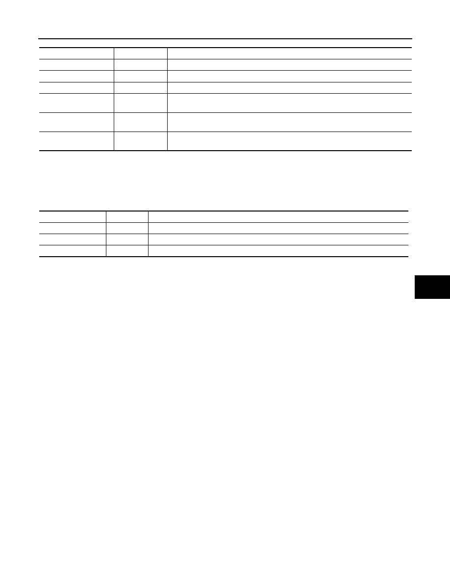
ACTIVE TEST

CONSULT screen item

Indication/Unit

Description

BATTERY VOLTAGE

V

Battery voltage of the moment a particular DTC is detected.

VEHICLE SPEED

km/h

Vehicle speed of the moment a particular DTC is detected.

EXTERNAL TEMP

°

C

External temperature of the moment a particular DTC is detected

VEHICLE COND

NOTE:
This item is displayed, but cannot be use this item.

DOOR LOCK STATUS

NOTE:
This item is displayed, but cannot be use this item.

POWER SUPPLY 
COUNTER

min

Displays the cumulative time from the time that the battery terminal is connected.

Test item

Operation

Description

PTC RELAY-1

Off/On

PTC RELAY-1 is turned OFF/ON.

PTC RELAY-2

Off/On

PTC RELAY-2 is turned OFF/ON.

PTC RELAY-3

Off/On

PTC RELAY-3 is turned OFF/ON.

HAC-168

< ECU DIAGNOSIS INFORMATION >

[MANUAL AIR CONDITIONING]

A/C AMP.

ECU DIAGNOSIS INFORMATION

A/C AMP.

Reference Value

INFOID:0000000010939827

CONSULT DATA MONITOR REFERENCE VALUES

NOTE:
The following table includes information (items) inapplicable to this vehicle. For information (items) applicable
to this vehicle, refer to CONSULT display items.

TERMINAL LAYOUT

PHYSICAL VALUES

Monitor item

Condition

Value/Status

AMB TEMP SEN

Ignition switch ON

Equivalent to ambient tem-
perature

INT TEMP SEN

Ignition switch ON

Values depending on evapo-
rator fin temperature

AMB SEN CAL

Ignition switch ON

Equivalent to ambient tem-
perature

INT TEMP CAL

Ignition switch ON

Values depending on evapo-
rator fin temperature

COMP REQ SIG

Engine: Run at idle after 
warming up 

A/C switch: ON
(Compressor operation sta-
tus) 

On

A/C switch: OFF

Off

COMP ECV DUTY

Engine: Run at idle after 
warming up 

A/C switch: ON
(Compressor operation sta-
tus) 

1 - 100%

A/C switch: OFF

0%

FAN REQ SIG

Engine: Run at idle after 
warming up 

Blower motor: ON

On

Blower motor: OFF

Off

FAN DUTY

Engine: Run at idle after 
warming up 

Blower motor: ON

1 – 100

Blower motor: OFF

0

VEHICLE SPEED

Turn drive wheels and compare CONSULT value with the 
speedometer indication.

Equivalent to speedometer 
reading

JMIIA3431ZZ

A/C AMP.

HAC-169

< ECU DIAGNOSIS INFORMATION >

[MANUAL AIR CONDITIONING]

C

D

E

F

G

H

J

K

L

M

A

B

HAC

N

O

P

Terminal No.

(Wire color)

Description

Condition

Value

+

Signal name

Input/

Output

1

(G)

Ground

Fan control amp. control

Output

Ignition 
switch ON

Blower mo-
tor: 1st - 23rd 
speed (man-
ual)

2.5 – 3.5 V

Blower mo-
tor: 24th 
speed (man-
ual)

10 – 11 V

3

(SB)

Ground

Accessory power supply

Input

Ignition switch ON

11 – 14 V

4

(V)

Ground

Ignition power supply

Input

Ignition switch ON

11 – 14 V

7

(L)

CAN-H

Input/

Output

8

(W)

Ground

Door motor power supply (mode, 
intake)

Output

• Ignition switch ON
• Each following condition
- Immediately after the IN-

TAKE switch is operated 
(when intake door motor 
operates)

- Immediately after the 

MODE VENT/FOOT/DEF 
switch is operated (when 
mode door motor oper-
ates)

11 – 14 V

9

(BG)

Ground

Air mix door motor drive 1

Output

• Ignition switch ON
• Immediately after the tem-

perature control dial is op-
erated (when the air mix 
door motor operates)

10

(Y)

Ground

Air mix door motor drive 2

11

(V)

Ground

Intake door motor drive 1

Output

• Ignition switch ON
• Immediately after the IN-

TAKE switch is operated 
(when intake door motor 
operates)

12

(GR)

Ground

Intake door motor drive 2

13

(LG)

Ground

Mode door motor drive 1

Output

• Ignition switch ON
• Immediately after the 

MODE VENT/FOOT/DEF 
switch is operated (when 
mode door motor oper-
ates)

14

(SB)

Ground

Mode door motor drive 2

17

(W)

Ground

Blower motor feedback

Output

Ignition 
switch ON

Blower mo-
tor: 1st 
speed (man-
ual)

9.0 – 10.5 V

JPIIA1647GB

JPIIA1647GB

JPIIA1647GB

HAC-170

< ECU DIAGNOSIS INFORMATION >

[MANUAL AIR CONDITIONING]

A/C AMP.

18

(BR)

Ground

Sensor ground (intake)

Ignition switch ON

0 – 0.1 V

19

(B)

Ground

Ground

Ignition switch ON

0 – 0.1 V

21

(BG)

Ground

Intake sensor

Input

Air tempera-
ture after 
passing 
through 
evaporator
(Ignition 
switch ON)

20

°

C

(

4

°

F)

4.41 V

10

°

C

(14

°

F)

4.09 V

0

°

C

(32

°

F)

3.68 V

10

°

C

(50

°

F)

3.21 V

20

°

C

(68

°

F)

2.71 V

25

°

C

(77

°

F)

2.47 V

30

°

C

(86

°

F)

2.23 V

40

°

C

(104

°

F)

1.80 V

23

(R)

CAN-L

Input/

Output

24

(SB)

Ground

Door motor power supply (air 
mix)

Output

• Ignition switch ON
• Following condition
- Immediately after the tem-

perature control dial is op-
erated

11 – 14 V

25

(GR)

Ground

Air mix door motor drive 3

Output

• Ignition switch ON
• Immediately after the tem-

perature control dial is op-
erated (when the air mix 
door motor operates)

26

(BR)

Ground

Air mix door motor drive 4

27

(LG)

Ground

Intake door motor drive 3

Output

• Ignition switch ON
• Immediately after the IN-

TAKE switch is operated 
(when intake door motor 
operates)

28

(W)

Ground

Intake door motor drive 4

29

(BG)

Ground

Mode door motor drive 3

Output

• Ignition switch ON
• Immediately after the 

MODE VENT/FOOT/DEF 
switch is operated (when 
mode door motor oper-
ates)

30

(G)

Ground

Mode door motor drive 4

Terminal No.

(Wire color)

Description

Condition

Value

+

Signal name

Input/

Output

JPIIA1647GB

JPIIA1647GB

JPIIA1647GB


содержание   ..  1421  1422  1423  1424   ..