Nissan X-Trail 32. Manual - part 1419


  Главная      Nissan     Nissan X-Trail 32 - Service Manual


поиск по сайту            


содержание   ..  1417  1418  1419  1420   ..


Nissan X-Trail 32. Manual - part 1419


SYSTEM

HAC-151

< SYSTEM DESCRIPTION >

[MANUAL AIR CONDITIONING]

C

D

E

F

G

H

J

K

L

M

A

B

HAC

N

O

P

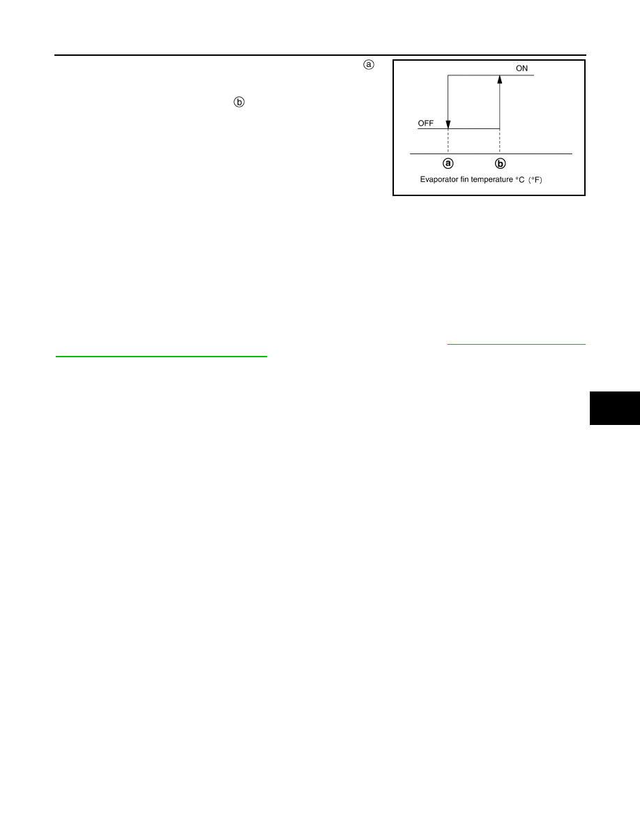
When intake sensor detects that evaporator fin temperature is 

 [

5.0

°

C (23.0

°

F)] or less, A/C amp. requests ECM to turn the compres-

sor OFF, and stops the compressor.
When the air temperature returns to 

 [1.0

°

C (33.8

°

F)] or more, the

compressor is activated.

Refrigerant Discharge Amount Control

• A/C amp. transmits the ECV control signal via CAN communication. IPDM E/R transmits the control signal to

ECV according to the received ECV control signal.

• ECV is controlled according to change in the duty ratio of the transmitted control signal.
• Except when temperature setting is full cold or outlet is DEF, A/C amp. controls the refrigerant discharge

amount according to the required cooling capacity.

• A/C amp. increases the refrigerant discharge amount when evaporator temperature is higher than the target

temperature upper limit, and reduces the refrigerant discharge amount when evaporator temperature is at or
below the target temperature upper limit.

NOTE:
Target temperature upper limit value of evaporator can be changed using “TARGET EVAPORATOR TEMP
UPPER LIMIT SETTING” in “WORK SUPPORT” mode of CONSULT. Refer to 

HAC-188, "Setting of Target

Evaporator Temperature Upper Limit Value"

.

Compressor Oil Circulation Control

When the engine starts, A/C amp. activates the compressor for a few seconds and circulates the compressor
oil once.

CONTROL BY ECM

Compressor Protection Control at Pressure Malfunction

When the high-pressure side value that is detected by refrigerant pressure sensor is as per the following state,
ECM requests IPDM E/R to turn A/C relay OFF and stops the compressor.
• 3.12 MPa (31.82 kg/cm

2

, 452.4 psi) or more (When the engine speed is less than 1,500 rpm)

• 2.74 MPa (27.95 kg/cm

2

, 397.3 psi) or more (When the engine speed is 1,500 rpm or more)

• 0.14 MPa (1.43 kg/cm

2

, 20.3 psi) or less

Air Conditioning Cut Control

When the engine condition is high load, ECM transmit A/C relay OFF request to IPDM E/R, and stops the
compressor.

MANUAL AIR CONDITIONING SYSTEM : Door Control

INFOID:0000000010939818

SWITCH AND THEIR CONTROL FUNCTION

JMIIA2550GB

HAC-152

< SYSTEM DESCRIPTION >

[MANUAL AIR CONDITIONING]

SYSTEM

*: R9M engine models
NOTE:
The sub-defroster and side ventilator door include a permanent opening and does not fully close.

Intake door

Blower motor

Air conditioner filter

Evaporator

Heater core

PTC heater*

Air mix door

Foot door

Side ventilator door

Sub defroster door

Center ventilator and defroster door

Fresh air

Recirculation air

Discharge air

Defroster

Center ventilator

Side ventilator

Rear ventilator

Front foot

Rear foot

JMIIA3570ZZ

SYSTEM

HAC-153

< SYSTEM DESCRIPTION >

[MANUAL AIR CONDITIONING]

C

D

E

F

G

H

J

K

L

M

A

B

HAC

N

O

P

AIR DISTRIBUTION

With rear ventilator, with rear foot

MANUAL AIR CONDITIONING SYSTEM : Cooling Fan Control

INFOID:0000000010939819

DESCRIPTION

A/C amp. controls the cooling fan operation request according to the refrigerant pressure status and vehicle
speed status.
NOTE:

Switch/dial position

Door position

Mode door

Intake door

Air mix 

door

Ce

nt

e

r v

e

n

til

at

o

r a

n

d

 de

fr

ost

e

do

or

S

u

b

 de

fros

te

r do

or

Si

de

 v

e

n

til

at

o

do

or

Fo

ot doo

r

• MODE VENT switch
• MODE FOOT switch
• MODE DEF switch
• MAX DEF switch

MODE 
position

VENT/DEF (V/D)

VENT

Bi-level (B/L)

ALL

FOOT

DEF/FOOT (D/F)

DEF

INTAKE switch

REC

FRE

Temperature control dial

Full cold

Full cold – Full hot

 - 

Full hot

Discharge air flow

MODE position

Air outlet/distribution

Ventilator

Foot

Defroster

Front

Rear

Front

Rear

Center

Side

V/D

39%

27%

11%

23%

VENT

47%

38%

15%

B/L

25%

34%

13%

18%

10%

ALL

21%

27%

11%

20%

10%

11%

FOOT

7%

4%

38%

24%

27%

D/F

6%

2%

30%

17%

45%

DEF

8%

2%

90%

HAC-154

< SYSTEM DESCRIPTION >

[MANUAL AIR CONDITIONING]

SYSTEM

For an overview of the cooling fan and information about control, refer to 

EC-57, "COOLING FAN CONTROL :

System Description"

 (MR20DD engine models) or 

EC-843, "COOLING FAN CONTROL : System Description"

(R9M engine models).

CONTROL OUTLINE

• A/C amp. receives the refrigerant pressure sensor signal from ECM via CAN communication, and the vehi-

cle speed signal from the combination meter via CAN communication.

• A/C amp. sets one of the optionally determined stages according to the received refrigerant pressure sensor

signal and vehicle speed signal.
NOTE:
For the rules that prescribe the predetermined stages, refer to the following figures.
• Vehicle speed stages

Vehicle speed [Km/h (MPH)]

-

: 12 (7.5)

-

: 20 (12)

-

: 72 (45)

-

: 80 (50)

• Refrigerant pressure stages

Refrigerant pressure [MPa (bar, kg/cm

2

, psi)]

-

: 0.7 (7, 7.14, 102)

-

: 1.0 (10, 10.2, 145)

-

: 1.28 (12.8, 13.1, 186)

-

: 1.58 (15.8, 16.1, 229)

-

: 1.88 (18.8, 19.2, 273)

-

: 2.08 (20.8, 21.2, 302)

• The requested cooling fan operation strength (0%, 40%, 100%) is determined as shown in the following

table according to the combination of these two stages, and the request signal is transmitted to ECM via
CAN communication.

Cooling fan operation strength

Unit: %

MANUAL AIR CONDITIONING SYSTEM : Door Motor Starting Position Reset Control

INFOID:0000000010939820

• Step motors are used for the mode door motor air mix door motor, and intake door motor.
• Because the step motors do not have position detection mechanisms, there may be a deviation between the

door position recognized by A/C amp. and the actual door position.
Therefore, A/C amp. performs motor zero position reset for aligning its recognized door position with the
actual door position.

• The reset signal is transmitted from A/C amp. to the air mix door motor, mode door motor, and intake door

motor, which then perform zero position reset.

• After any of the following conditions is met, A/C amp. performs motor zero position reset when the ignition

switch is next turned ON.

JMIIA3568GB

JMIIA3569GB

Refrigerant pressure stages

1

2

3

4

Vehicle speed stag-
es

1

40

40

100

100

2

40

40

100

100

3

0

0

0

100


содержание   ..  1417  1418  1419  1420   ..