Nissan X-Trail 32. Manual - part 1388


  Главная      Nissan     Nissan X-Trail 32 - Service Manual


поиск по сайту            


содержание   ..  1386  1387  1388  1389   ..


Nissan X-Trail 32. Manual - part 1388


SYSTEM

HAC-27

< SYSTEM DESCRIPTION >

[AUTOMATIC AIR CONDITIONING]

C

D

E

F

G

H

J

K

L

M

A

B

HAC

N

O

P

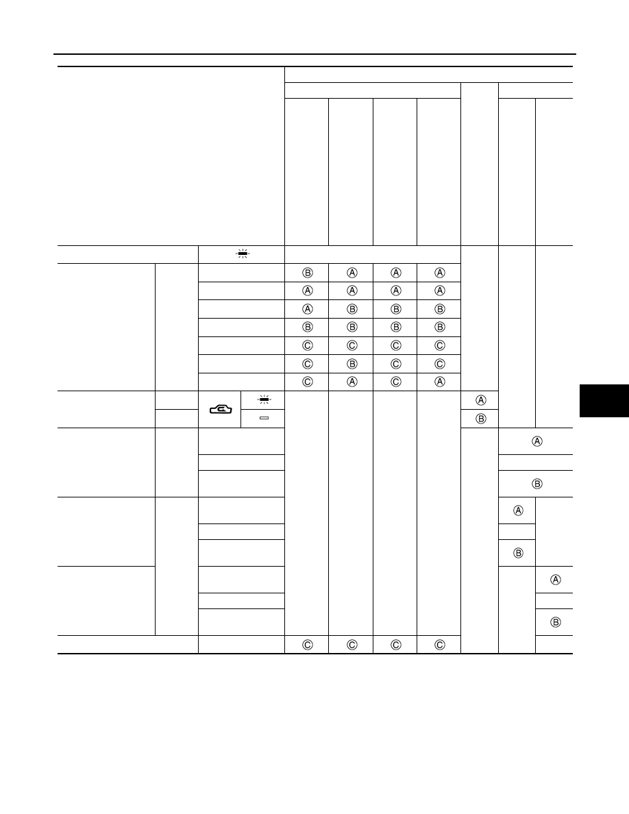
*: Air inlet status is displayed by indicator during activating automatic control

AIR DISTRIBUTION

Switch/dial position

Door position

Mode door

In

ta

k

e

 do

or

Air mix door

Ce

nt

e

r v

e

n

til

at

o

r a

n

d

 de

fr

ost

e

do

or

S

u

b

 de

fros

te

r do

or

Si

de

 v

e

n

til

at

o

do

or

Fo

ot doo

r

Driver side

Pa

ss

en

ge

r si

de

AUTO switch

AUTO

• MODE VENT switch
• MODE FOOT switch
• MODE DEF switch
• MAX DEF switch

MODE 
position

VENT/DEF (V/D)

VENT

Bi-level (B/L)

ALL

FOOT

DEF/FOOT (D/F)

DEF

INTAKE switch*

REC

FRE

Temperature control 
dial (Driver side)

DUAL 
switch: 
OFF

Full cold

Lo

16.0

°

C – 30.0

°

C

AUTO

Full hot

HI

Temperature control 
dial (Driver side)

DUAL 
switch: 
ON

Full cold

Lo

16.0

°

C – 30.0

°

C

AUTO

Full hot

HI

Temperature control 
dial (Passenger side)

Full cold

Lo

16.0

°

C – 30.0

°

C

AUTO

Full hot

HI

ON·OFF switch

OFF

HAC-28

< SYSTEM DESCRIPTION >

[AUTOMATIC AIR CONDITIONING]

SYSTEM

AUTOMATIC AIR CONDITIONING SYSTEM : Cooling Fan Control

INFOID:0000000010939707

DESCRIPTION

A/C auto amp. controls the cooling fan operation request according to the refrigerant pressure status and vehi-
cle speed status.
NOTE:
For an overview of the cooling fan and information about control, refer to 

EC-57, "COOLING FAN CONTROL :

System Description"

 (MR20DD engine models), 

EC-472, "COOLING FAN CONTROL : System Description"

(QR25DE engine models) or 

EC-843, "COOLING FAN CONTROL : System Description"

 (R9M engine mod-

els).

CONTROL OUTLINE

• A/C auto amp. receives the refrigerant pressure sensor signal from ECM via CAN communication, and the

vehicle speed signal from the combination meter via CAN communication.

• A/C auto amp. sets one of the optionally determined stages according to the received refrigerant pressure

sensor signal and vehicle speed signal.
NOTE:
For the rules that prescribe the predetermined stages, refer to the following figures.
• Vehicle speed stages

Vehicle speed [Km/h (MPH)]

-

: 12 (7.5)

-

: 20 (12)

-

: 72 (45)

-

: 80 (50)

• Refrigerant pressure stages

Refrigerant pressure [MPa (bar, kg/cm

2

, psi)]

-

: 0.7 (7, 7.14, 102)

-

: 1.0 (10, 10.2, 145)

-

: 1.28 (12.8, 13.1, 186)

-

: 1.58 (15.8, 16.1, 229)

-

: 1.88 (18.8, 19.2, 273)

-

: 2.08 (20.8, 21.2, 302)

Discharge air flow

MODE position

Air outlet/distribution

Ventilator

Foot

Defroster

Front

Rear

Front

Rear

Center

Side

V/D

39%

27%

11%

23%

VENT

47%

38%

15%

B/L

25%

34%

13%

18%

10%

ALL

21%

27%

11%

20%

10%

11%

FOOT

7%

4%

38%

24%

27%

D/F

6%

2%

30%

17%

45%

DEF

8%

2%

90%

JMIIA3568GB

JMIIA3569GB

SYSTEM

HAC-29

< SYSTEM DESCRIPTION >

[AUTOMATIC AIR CONDITIONING]

C

D

E

F

G

H

J

K

L

M

A

B

HAC

N

O

P

• The requested cooling fan operation strength (0%, 40%, 100%) is determined as shown in the following

table according to the combination of these two stages, and the request signal is transmitted to ECM via
CAN communication.

Cooling fan operation strength

Unit: %

AUTOMATIC AIR CONDITIONING SYSTEM : Door Motor Starting Position Reset 
Control

INFOID:0000000010939708

• Step motors are used for the mode door motor air mix door motor (driver side/passenger side), and intake

door motor.

• Because the step motors do not have position detection mechanisms, there may be a deviation between the

door position recognized by A/C auto amp. and the actual door position.
Therefore, A/C auto amp. performs motor zero position reset for aligning its recognized door position with
the actual door position.

• The reset signal is transmitted from A/C auto amp. to the air mix door motor (driver side/passenger side),

mode door motor, and intake door motor, which then perform zero position reset.

• After any of the following conditions is met, A/C auto amp. performs motor zero position reset when the igni-

tion switch is next turned ON.

- The battery terminal is disconnected and then reconnected.
- The travel distance reaches 3,000 km (1846 miles). [Performed every 3,000 km (1846 miles).]
• If A/C auto amp., air mix door motor (driver side, passenger side), mode door motor, or intake door motor is

removed, it is necessary to perform motor zero position reset using CONSULT.

Refrigerant pressure stages

1

2

3

4

Vehicle speed stag-
es

1

40

40

100

100

2

40

40

100

100

3

0

0

0

100

HAC-30

< SYSTEM DESCRIPTION >

[AUTOMATIC AIR CONDITIONING]

SYSTEM

AUTOMATIC AIR CONDITIONING SYSTEM : Circuit Diagram

INFOID:0000000010941032

MR20DD AND QR25DE ENGINE MODELS

JMIIA3665GB


содержание   ..  1386  1387  1388  1389   ..