Nissan X-Trail 32. Manual - part 1387


  Главная      Nissan     Nissan X-Trail 32 - Service Manual


поиск по сайту            


содержание   ..  1385  1386  1387  1388   ..


Nissan X-Trail 32. Manual - part 1387


SYSTEM

HAC-23

< SYSTEM DESCRIPTION >

[AUTOMATIC AIR CONDITIONING]

C

D

E

F

G

H

J

K

L

M

A

B

HAC

N

O

P

AUTOMATIC AIR CONDITIONING SYSTEM : Air Outlet Control

INFOID:0000000010939702

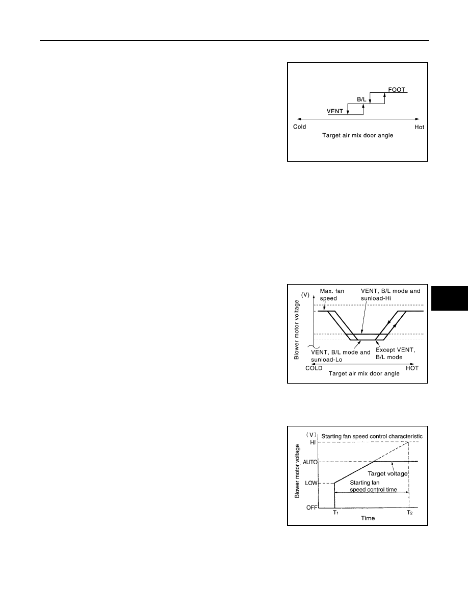
• While air outlet is in automatic control, A/C auto amp. selects the

mode door position depending on a target air mix door angle and
outlet air temperature calculated from sunload.

• If ambient temperature is excessively low, D/F is selected to pre-

vent windshield fogging when air outlet is set to FOOT.

AUTOMATIC AIR CONDITIONING SYSTEM : Air Flow Control

INFOID:0000000010939703

DESCRIPTION

• A/C auto amp. changes gate voltage of power transistor and controls air flow continuously. When air flow is

increased, voltage of blower motor gradually increases to prevent a sudden increase in air flow.

• In addition to manual control and automatic control, air flow control is compose of starting fan speed control,

low coolant temperature starting control, high in-vehicle temperature starting control, and blower speed con-
trol at door motor operation.

AUTOMATIC AIR FLOW CONTROL

• A/C auto amp. decides target air flow depending on target air mix door opening angle.
• A/C auto amp. changes voltage of blower motor and controls air flow continuously so that air flow matches to

target air flow.

• When air outlet is VENT or B/L, the minimum air flow is changed

depending on sunload.

STARTING FAN SPEED CONTROL

When blower motor is activated, A/C auto amp. gradually increases voltage of blower motor to prevent a sud-
den increase in discharge air flow. (T

1 –

 T

2

 = approximately 5 seconds)

NOTE:
Do not perform the starting air flow control when the discharge outlet
is set to DEF.

LOW COOLANT TEMPERATURE STARTING CONTROL

JMIIA0710GB

JMIIA1129GB

JMIIA1130GB

HAC-24

< SYSTEM DESCRIPTION >

[AUTOMATIC AIR CONDITIONING]

SYSTEM

If the engine coolant temperature is 56

°

C (133

°

F) or less, to prevent

a cold discharged air flow, A/C auto amp. suspends blower motor
activation for the maximum 150 seconds depending on target air mix
door opening angle. After this, voltage of blower motor is increased
gradually, and blower motor is activated.

HIGH IN-VEHICLE TEMPERATURE STARTING CONTROL

When evaporator temperature is high [intake sensor value is 35

°

C (95

°

F) or more], to prevent a hot dis-

charged air flow, A/C auto amp. suspends blower motor activation for approximately 3 seconds so that evapo-
rator is cooled by refrigerant.

FAN SPEED CONTROL AT DOOR MOTOR OPERATION

When mode door motor is activated while air flow is more than the specified value, A/C auto amp. reduces
temporarily fan speed so that mode door moves smoothly.

AUTOMATIC AIR CONDITIONING SYSTEM : Air Inlet Control

INFOID:0000000010939704

• A/C auto amp. controls intake door motor, and change air inlet.
• While air inlet is in automatic control, A/C auto amp. selects air

inlet (fresh air intake, 20% fresh air intake, or recirculation)
depending on set temperature, in-vehicle temperature, and ambi-
ent temperature.

AUTOMATIC AIR CONDITIONING SYSTEM : Compressor Control

INFOID:0000000010939705

DESCRIPTION

• When the compressor activation condition is satisfied while blower motor is activated, A/C auto amp. trans-

mits A/C ON signal and blower fan ON signal to ECM.

• ECM judges the conditions of each sensor (Refrigerant pressure sensor signal, accelerator position signal,

etc.), and transmits the A/C compressor request signal to IPDM E/R via CAN communication line.

• By receiving the A/C compressor request signal from ECM, IPDM E/R turns the A/C relay to ON, and acti-

vates the compressor. Refer to 

PCS-7, "RELAY CONTROL SYSTEM : System Description"

.

CONTROL BY A/C AUTO AMP.

Low Temperature Protection Control

When intake sensor detects that evaporator fin temperature is 

 [

5.0

°

C (23.0

°

F)] or less, A/C auto amp. requests ECM to turn the

compressor OFF, and stops the compressor.
When the air temperature returns to 

 [1.0

°

C (33.8

°

F)] or more, the

compressor is activated.

Refrigerant Discharge Amount Control

JMIIA1227GB

JMIIA0711GB

JMIIA2550GB

SYSTEM

HAC-25

< SYSTEM DESCRIPTION >

[AUTOMATIC AIR CONDITIONING]

C

D

E

F

G

H

J

K

L

M

A

B

HAC

N

O

P

• A/C auto amp. transmits the ECV control signal via CAN communication. IPDM E/R transmits the control sig-

nal to ECV according to the received ECV control signal.

• ECV is controlled according to change in the duty ratio of the transmitted control signal.
• Except when temperature setting is full cold or outlet is DEF, A/C auto amp. controls the refrigerant dis-

charge amount according to the required cooling capacity.

• A/C auto amp. increases the refrigerant discharge amount when evaporator temperature is higher than the

target temperature upper limit, and reduces the refrigerant discharge amount when evaporator temperature
is at or below the target temperature upper limit.

NOTE:
Target temperature upper limit value of evaporator can be changed using “TARGET EVAPORATOR TEMP
UPPER LIMIT SETTING” in “WORK SUPPORT” mode of CONSULT. Refer to 

HAC-75, "Setting of Target

Evaporator Temperature Upper Limit Value"

.

Compressor Oil Circulation Control

When the engine starts, A/C auto amp. activates the compressor for a few seconds and circulates the com-
pressor oil once.

CONTROL BY ECM

Compressor Protection Control at Pressure Malfunction

When the high-pressure side value that is detected by refrigerant pressure sensor is as per the following state,
ECM requests IPDM E/R to turn A/C relay OFF and stops the compressor.
• 3.12 MPa (31.82 kg/cm

2

, 452.4 psi) or more (When the engine speed is less than 1,500 rpm)

• 2.74 MPa (27.95 kg/cm

2

, 397.3 psi) or more (When the engine speed is 1,500 rpm or more)

• 0.14 MPa (1.43 kg/cm

2

, 20.3 psi) or less

Air Conditioning Cut Control

When the engine condition is high load, ECM transmit A/C relay OFF request to IPDM E/R, and stops the
compressor.

AUTOMATIC AIR CONDITIONING SYSTEM : Door Control

INFOID:0000000010939706

SWITCH AND THEIR CONTROL FUNCTION

HAC-26

< SYSTEM DESCRIPTION >

[AUTOMATIC AIR CONDITIONING]

SYSTEM

*: R9M engine models
NOTE:
The sub-defroster and side ventilator door include a permanent opening and does not fully close.

Intake door

Blower motor

Air conditioner filter

Evaporator

Heater core

PTC heater*

Air mix door (driver side/passenger 
side)

Foot door

Side ventilator door

Sub defroster door

Center ventilator and defroster door

Fresh air

Recirculation air

Discharge air

Defroster

Center ventilator

Side ventilator

Rear ventilator

Front foot

Rear foot

JMIIA3570ZZ


содержание   ..  1385  1386  1387  1388   ..