содержание .. 1356 1357 1358 1359 ..
Nissan X-Trail 32. Manual - part 1358
A/C UNIT ASSEMBLY
HA-91
< REMOVAL AND INSTALLATION >
[MR20DD]
C
D
E
F
G
H
J
K
L
M
A
B
HA
N
O
P
HEATER CORE : Removal and Installation
INFOID:0000000011001073
REMOVAL
1.
Remove A/C unit assembly. Refer to
HA-88, "A/C UNIT ASSEMBLY : Removal and Installation"
.
2.
Remove foot duct LH. Refer to
VTL-12, "FOOT DUCT : Removal and Installation"
.
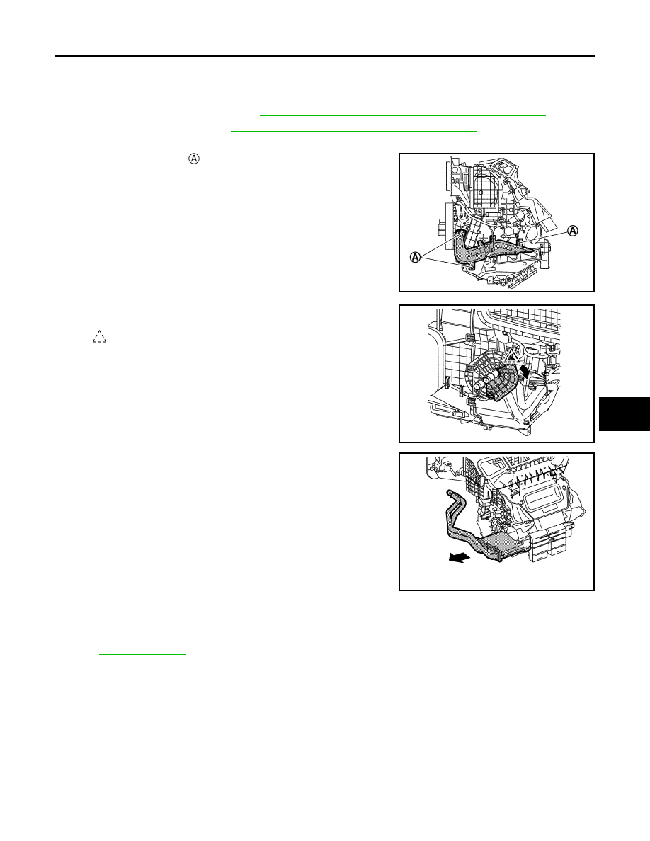
3.
Remove heater pipe grommet.
4.
Remove fixing screws
, and then remove heater pipe cover.
5.
Disengage fixing pawl, and then remove heater pipe bracket.
6.
Slide heater core to left side, and then remove heater core.
INSTALLATION
Note the following item, and then install in the reverse order of removal.
NOTE:
Refer to
when filling radiator with engine coolant.
EVAPORATOR
EVAPORATOR : Removal and Installation
INFOID:0000000011001074
REMOVAL
1.
Remove A/C unit assembly. Refer to
HA-88, "A/C UNIT ASSEMBLY : Removal and Installation"
.
2.
Disassemble A/C unit assembly, and then remove evaporator assembly.
3.
Remove mounting bolts, and then remove expansion valve from evaporator assembly.
INSTALLATION
Note the following items, and then install in the reverse order of removal.
JMIIA3386ZZ
: Pawl
JMIIA3387ZZ
JMIIA3388ZZ