Nissan X-Trail 32. Manual - part 1302


  Главная      Nissan     Nissan X-Trail 32 - Service Manual


поиск по сайту            


содержание   ..  1300  1301  1302  1303   ..


Nissan X-Trail 32. Manual - part 1302


FSU-12

< REMOVAL AND INSTALLATION >

FRONT COIL SPRING AND STRUT

Strut Assembly

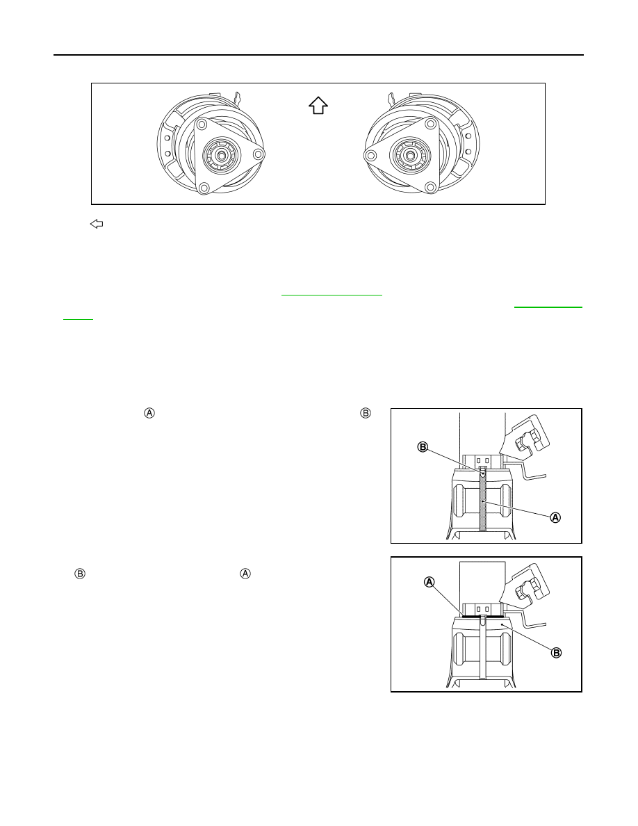
• When installing strut assembly to the vehicle, set the mounting insulator to the direction shown in the figure.

CAUTION:

Never reuse strut mounting nut.

• Perform final tightening of fixing parts at the vehicle installation position (rubber bushing), under unladen

conditions with tires on level ground.

• Perform inspection after installation. Refer to 

FSU-15, "Inspection"

.

• After replacing the strut, always follow the disposal procedure to discard the strut. Refer to 

FSU-16, "Dis-

posal"

.

Strut Assembly and Steering Knuckle Connection

CAUTION:

Be sure to remove lubricants if lubricant has been used to separate the connection of strut assembly
and steering knuckle.
Install the steering knuckle to strut assembly as follows.

1.

Set suitable jack under steering knuckle. 

2.

Align the gap 

 of steering knuckle to the projection part 

 of

strut.

3.

Tighten the mounting bolt with pushing up the steering knuckle

 until contacts stopper bracket 

 end face, using a suitable

jack.

CAUTION:

Check the stable condition when using a jack.

Disassembly and Assembly

INFOID:0000000010822755

DISASSEMBLY

CAUTION:

Never damage strut assembly piston rod when removing components from strut assembly.

: Vehicle front

JMEIA0222ZZ

JMEIA0223ZZ

JMEIA0224ZZ

FRONT COIL SPRING AND STRUT

FSU-13

< REMOVAL AND INSTALLATION >

C

D

F

G

H

I

J

K

L

M

A

B

FSU

N

O

P

1.

Install strut attachment (A) (SST: ST35652000) to strut assem-
bly and secure it in a vise.

CAUTION:

When installing the strut attachment to strut assembly,
wrap a shop cloth around strut to protect from damage.

2.

Using a spring compressor (A) (commercial service tool), com-
press coil spring between spring upper seat and lower seat
(strut assembly) until coil spring with a spring compressor is
free.

CAUTION:

Be sure a spring compressor is securely attached to coil
spring. Compress coil spring.

3.

Check coil spring with a spring compressor between spring upper seat and lower seat (strut assembly) is
free. And then remove piston rod lock nut while securing the piston rod tip so that piston rod does not turn.

4.

Remove mounting insulator, mounting bearing, upper rubber seat and bound bumper from strut.

5.

After removing coil spring with a spring compressor (commercial service tool), then gradually release a
spring compressor.

CAUTION:

Loosen while making sure coil spring attachment position does not move.

6.

Remove lower rubber seat.

7.

Remove strut attachment (A) (SST: ST35652000) from strut.

8.

Perform inspection after disassembly. Refer to 

FSU-15, "Inspection"

.

ASSEMBLY

CAUTION:

Never damage strut assembly piston rod when installing components from strut assembly.

1.

Install strut attachment (SST: ST35652000) to strut and secure it in a vise.

CAUTION:

When installing the strut attachment to strut assembly, wrap a shop cloth around strut to protect
from damage.

JPEIA0006ZZ

JPEIA0007ZZ

JPEIA0006ZZ

FSU-14

< REMOVAL AND INSTALLATION >

FRONT COIL SPRING AND STRUT

2.

Install lower rubber seat with its protrusion 

 on the lower area

aligned with the hole 

 on the strut.

3.

Compress coil spring using a spring compressor (commercial service tool), and install it onto strut assem-
bly.

CAUTION:

• Be sure a spring compressor is securely attached to coil spring, before compress coil spring.
• Align the lower end of coil spring 

 with lower rubber

seat 

 as shown in the figure.

• Set coil spring so that its paint marks 

 is aligned with

the position of 1.75 turns from the bottom end of the coil
spring.

4.

Apply soapy water to bound bumper.

CAUTION:

Never use machine oil.

5.

Set bound bumper to piston rod of strut.

6.

Install mounting bearing, mounting insulator and upper rubber seat on to spring.

CAUTION:

Never apply oils, such as grease, when installing the mounting bearing and mounting insulator.

7.

Set the mounting insulator to the direction shown in the figure, and then install the mounting insulator, the
upper rubber seat and the mounting bearing to the strut.

JSEIA0892ZZ

Dimension (A)

: 5 mm (0.20 in) or less

JSEIA0658ZZ

: Upper side

JSEIA0893ZZ

JMEIA0222ZZ

FRONT COIL SPRING AND STRUT

FSU-15

< REMOVAL AND INSTALLATION >

C

D

F

G

H

I

J

K

L

M

A

B

FSU

N

O

P

CAUTION:

• Align the upper end of coil spring with upper rubber seat

as shown in the figure.

8.

Secure piston rod tip so that piston rod does not turn, then tighten piston rod lock nut with specified
torque.

CAUTION:

Never reuse piston rod lock nut.

9.

Gradually release a spring compressor (A) (commercial service
tool), and remove coil spring.

CAUTION:

Loosen while making sure coil spring attachment position
does not move.

10. Remove the strut attachment (A) (SST: ST35652000) from strut

assembly.

Inspection

INFOID:0000000010822756

INSPECTION AFTER DISASSEMBLY

Check the following items, and replace the parts if necessary.

Strut

• Strut for deformation, cracks or damage
• Piston rod for damage, uneven wear or distortion
• Oil leakage

Strut Mounting Insulator and Bound Bumper

Check strut mounting insulator and bound bumper for cracks, wear or damage.

Coil Spring

Check coil spring for cracks, wear or damage.

INSPECTION AFTER INSTALLATION

1.

Check wheel sensor harness for proper connector. Refer to 

BRC-212, "FRONT WHEEL SENSOR :

Exploded View"

.

Dimension (A)

: 5 mm (0.20 in) or less

JSEIA0894ZZ

JPEIA0007ZZ

JPEIA0006ZZ


содержание   ..  1300  1301  1302  1303   ..