содержание .. 1287 1288 1289 1290 ..
Nissan X-Trail 32. Manual - part 1289
FUEL LEVEL SENSOR UNIT, FUEL FILTER AND FUEL PUMP ASSEMBLY
FL-11
< REMOVAL AND INSTALLATION >
[GASOLINE ENGINE MODEL]
C
D
E
F
G
H
I
J
K
L
M
A
FL
N
P
O
REMOVAL AND INSTALLATION
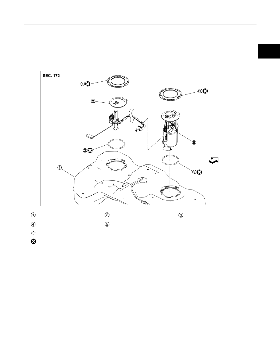
FUEL LEVEL SENSOR UNIT, FUEL FILTER AND FUEL PUMP ASSEMBLY
Exploded View
INFOID:0000000010778224
REMOVAL
DISASSEMBLY
Lock ring
Sub fuel level sensor assembly
O-ring
Fuel tank
Fuel level sensor unit, fuel filter and
fuel pump assembly
: Vehicle front
: Always replace after every disassembly.
JPBIA6852GB