содержание .. 1282 1283 1284 1285 ..
Nissan X-Trail 32. Manual - part 1284
FAX-128
< REMOVAL AND INSTALLATION >
[4WD]
FRONT DRIVE SHAFT
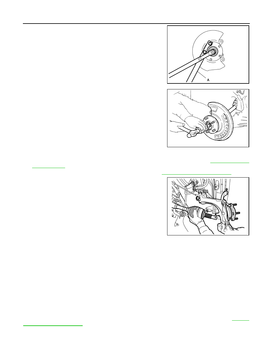
6.
Remove cotter pin, adjusting cap and then loosen wheel hub
lock nut, using a hub lock nut wrench (A) (SST: KV40104000).
7.
Patch wheel hub lock nut with a piece of wood. Hammer the
wood to disengage wheel hub and bearing assembly from drive
shaft.
NOTE:
Use suitable puller, if wheel hub and bearing assembly and drive
shaft cannot be separated even after performing the above pro-
cedure.
8.
Remove wheel hub lock nut.
9.
Remove transverse link from steering knuckle and front suspension member. Refer to
10. Separate steering outer socket from steering knuckle. Refer to
ST-22, "Removal and Installation"
11. Remove drive shaft from wheel hub and bearing assembly.
CAUTION:
• Never place drive shaft joint at an extreme angle.
• Be careful not to overextend slide joint.
12. Remove retainer mounting bolts and retainer.
13. Remove drive shaft from transaxle assembly.
• Use the drive shaft attachment (SST: KV40107500) and a sliding hammer while inserting tip of the drive
shaft attachment between housing and transaxle assembly.
CAUTION:
Never place drive shaft joint at an extreme angle when removing drive shaft. Also be careful not
to overextend slide joint.
14. If necessary, remove the support bearing bracket mounting bolts, support bearing bracket and the heat
insulator.
INSTALLATION
Left Side
Note the following, and install in the reverse order of removal.
CAUTION:
Always replace differential side oil seal with new one when installing drive shaft. Refer to
JSDIA2708ZZ
JPDIG0070ZZ
JSDIA5562ZZ