содержание .. 1280 1281 1282 1283 ..
Nissan X-Trail 32. Manual - part 1282
FAX-120
< REMOVAL AND INSTALLATION >
[4WD]
FRONT DRIVE SHAFT
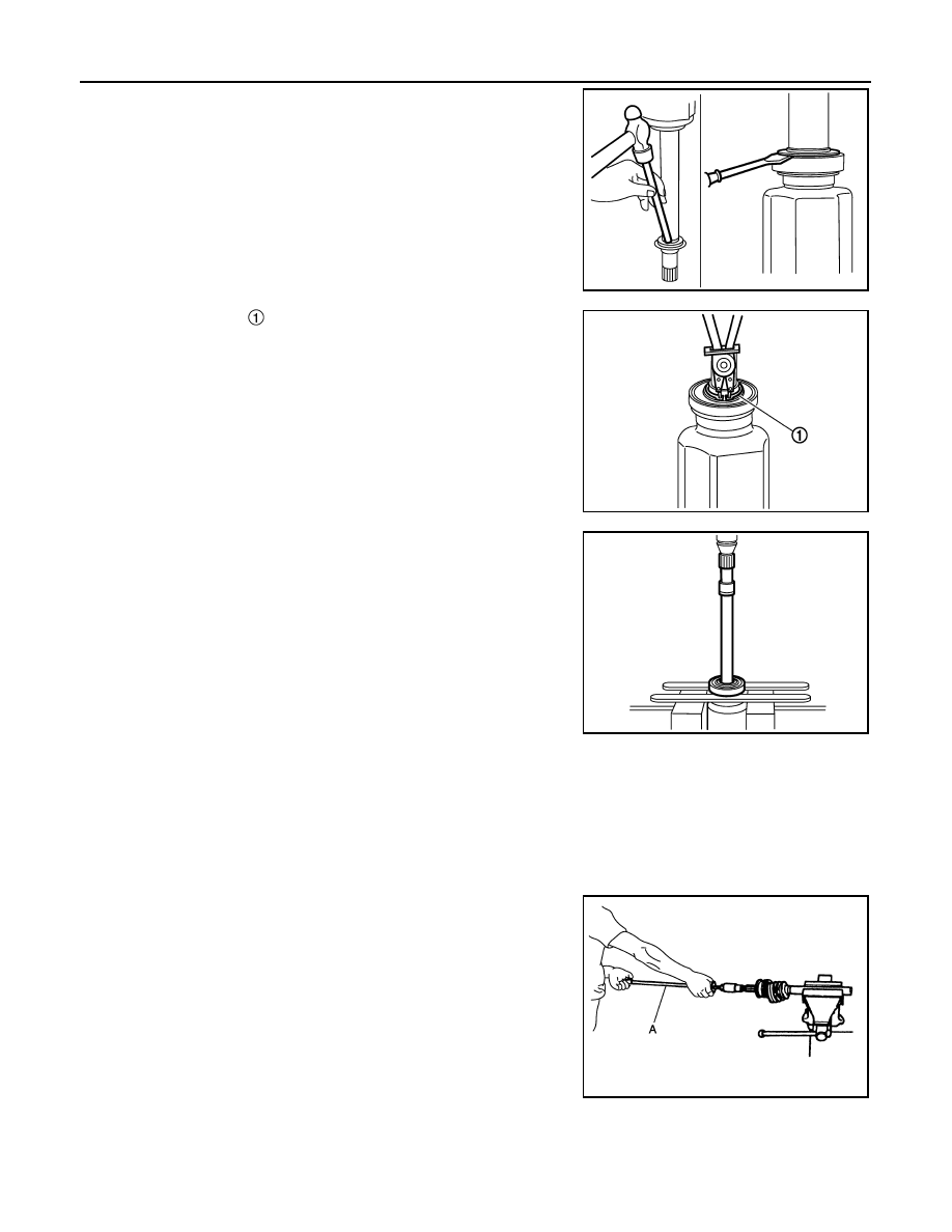
1.
Remove dust shield from housing.
2.
Remove snap ring
.
3.
Press out support bearing from housing.
4.
Remove dust shield.
Dynamic Damper
Remove damper bands, then remove dynamic damper from shaft.
Wheel Side
1.
Fix shaft with a vise.
CAUTION:
Protect shaft using aluminum or copper plates when fixing with a vise.
2.
Remove boot bands, and then remove boot from joint sub-assembly.
3.
Screw drive shaft puller (A) (commercial service tool) into joint
sub-assembly screw part to a length of 30 mm (1.18 in) or more.
Support drive shaft with one hand and pull out joint sub-assem-
bly from shaft.
CAUTION:
• If joint sub-assembly cannot be removed after five or
more unsuccessful attempts, replace shaft and joint sub
assembly as a set.
• Align sliding hammer and drive shaft and remove them by
pulling directory.
4.
Remove circular clip from shaft.
5.
Remove boot from shaft.
6.
Clean old grease on joint sub-assembly with paper towels while rotating ball cage.
ASSEMBLY
JPDIF0121ZZ
JPDIF0106ZZ
YAX004
JPDIG0151ZZ