Nissan X-Trail 32. Manual - part 1273


  Главная      Nissan     Nissan X-Trail 32 - Service Manual


поиск по сайту            


содержание   ..  1271  1272  1273  1274   ..


Nissan X-Trail 32. Manual - part 1273


FAX-84

< REMOVAL AND INSTALLATION >

[4WD]

FRONT DRIVE SHAFT BOOT

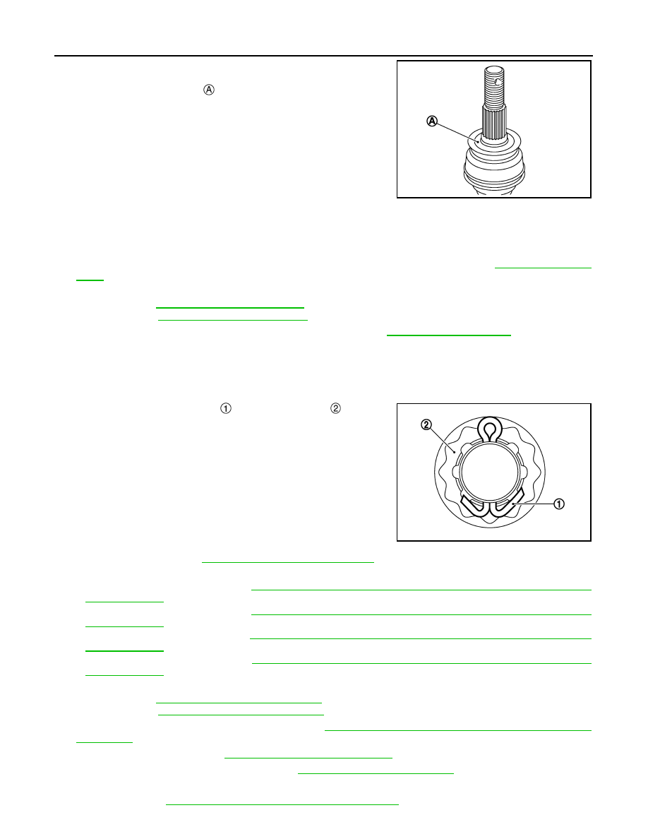
14. Clean the matching surface of drive shaft and wheel hub and

bearing assembly. And then apply paste [service parts
(440037S000)] to surface 

 of joint sub-assembly of drive shaft.

CAUTION:

Apply paste to cover entire flat surface of joint sub-assem-
bly of drive shaft.

15. Insert drive shaft to wheel hub and bearing assembly, and then temporarily tighten wheel hub lock nut.

CAUTION:

• Be sure to use torque wrench to tighten the wheel hub lock nut. Never use a power tool.
• Never reuse wheel hub lock nut.

16. Install transverse link to steering knuckle and front suspention member. Refer to 

FSU-17, "Exploded

View"

.

17. Install steering outer socket to steering knuckle.

• LHD: Refer to 

ST-20, "LHD : Exploded View"

.

• RHD: Refer to 

ST-21, "RHD : Exploded View"

.

18. Tighten the wheel hub lock nut to the specified torque. Refer to 

FAX-72, "Exploded View"

.

CAUTION:

• Since the drive shaft is assembled by press-fitting, use the tightening torque range for the wheel

hub lock nut.

• Be sure to use torque wrench to tighten the wheel hub lock nut. Never use a power tool.
• Never reuse wheel hub lock nut.

19. When installing a cotter pin 

 and adjusting cap 

, securely

bend the basal portion to prevent rattles.

CAUTION:

Never reuse cotter pin.

20. Install disc rotor. Refer to 

FAX-72, "Removal and Installation"

.

21. Install caliper assembly to steering knuckle.

• LHD (1 PISTON TYPE): Refer to 

BR-51, "BRAKE CALIPER ASSEMBLY (1 PISTON TYPE) : Removal

and Installation"

.

• LHD (2 PISTON TYPE): Refer to 

BR-56, "BRAKE CALIPER ASSEMBLY (2 PISTON TYPE) : Removal

and Installation"

.

• RHD (1 PISTON TYPE): Refer to 

BR-111, "BRAKE CALIPER ASSEMBLY (1 PISTON TYPE) : Removal

and Installation"

.

• RHD (2 PISTON TYPE): Refer to 

BR-56, "BRAKE CALIPER ASSEMBLY (2 PISTON TYPE) : Removal

and Installation"

.

22. Install lock plate to strut assembly.

• LHD: Refer to 

BR-24, "FRONT : Exploded View"

.

• RHD: Refer to 

BR-88, "FRONT : Exploded View"

.

23. Install wheel sensor to steering knuckle. Refer to 

BRC-212, "FRONT WHEEL SENSOR : Removal and

Installation"

.

24. Install tires to vehicle.Refer to 

WT-61, "Removal and Installation"

.

25. Perform inspection after installation. Refer to 

FAX-85, "MR20DD : Inspection"

.

Transaxle Side

• Installation: Refer to 

FAX-101, "MR20DD : Removal and Installation"

.

Amount paste

: 1.0 – 3.0 g (0.04 – 0.10 oz)

JPDIG0122ZZ

JPDIF0295ZZ

FRONT DRIVE SHAFT BOOT

FAX-85

< REMOVAL AND INSTALLATION >

[4WD]

C

E

F

G

H

I

J

K

L

M

A

B

FAX

N

O

P

• Assembly: Refer to 

FAX-107, "MR20DD : Disassembly and Assembly"

.

MR20DD : Inspection

INFOID:0000000010824412

INSPECTION AFTER REMOVAL

Check the following items, and replace the part if necessary.
• Check components for deformation, cracks, and other damage.
• Check boots of transverse link and steering outer socket ball joint for breakage, axial end play, and swing

torque.

- Transverse link: Refer to 

FSU-18, "Inspection"

.

- Steering outer socket: Refer to 

ST-26, "Inspection"

.

INSPECTION AFTER INSTALLATION

1.

Check wheel sensor harness for proper connection. Refer to 

BRC-212, "FRONT WHEEL SENSOR :

Exploded View"

2.

Check the wheel alignment. Refer to 

FSU-8, "Inspection"

.

3.

Adjust neutral position of steering angle sensor. Refer to 

BRC-99, "Work Procedure"

.

QR25DE

QR25DE : Exploded View

INFOID:0000000010824413

LEFT SIDE

JSDIA6398ZZ

Circular clip

Dust shield

Housing

Snap ring

Spider assembly

Stopper ring

Boot band

Boot

Shaft

Damper band

Dynamic damper

Joint sub-assembly

Dust shield

: Wheel side

1: Fill NISSAN Genuine grease or equivalent.

2: Apply paste [service parts (440037S000)]

: Always replace after every disassembly.

FAX-86

< REMOVAL AND INSTALLATION >

[4WD]

FRONT DRIVE SHAFT BOOT

RIGHT SIDE

QR25DE : Removal and Installation

INFOID:0000000010824414

REMOVAL

Wheel Side

1.

Remove tires. Refer to 

WT-61, "Removal and Installation"

.

2.

Remove wheel sensor from steering knuckle. Refer to 

BRC-212, "FRONT WHEEL SENSOR : Removal

and Installation"

.

JSDIA6399GB

Dust shield

Joint sub-assembly

Circular clip

Boot band

Boot

Shaft

Damper band

Dynamic damper

Stopper ring

Spider assembly

Snap ring

Housing

Dust shield

Support bearing

Retainer

Support bearing bracket

: Wheel side

1: Fill NISSAN Genuine grease or equivalent.

2: Apply paste [service parts (440037S000)].

: N·m (kg-m, ft-lb)

: Always replace after every disassembly.

FRONT DRIVE SHAFT BOOT

FAX-87

< REMOVAL AND INSTALLATION >

[4WD]

C

E

F

G

H

I

J

K

L

M

A

B

FAX

N

O

P

3.

Remove lock plate 

 from strut assembly.

• LHD: Refer to 

BR-24, "FRONT : Exploded View"

.

• RHD: Refer to 

BR-88, "FRONT : Exploded View"

.

4.

Remove caliper assembly. Hang caliper assembly in a place where it will not interfere with work.
• LHD (1 PISTON TYPE): Refer to 

BR-51, "BRAKE CALIPER ASSEMBLY (1 PISTON TYPE) : Removal

and Installation"

.

• LHD (2 PISTON TYPE): Refer to 

BR-56, "BRAKE CALIPER ASSEMBLY (2 PISTON TYPE) : Removal

and Installation"

.

• RHD (1 PISTON TYPE): Refer to 

BR-111, "BRAKE CALIPER ASSEMBLY (1 PISTON TYPE) : Removal

and Installation"

.

• RHD (2 PISTON TYPE): Refer to 

BR-116, "BRAKE CALIPER ASSEMBLY (2 PISTON TYPE) : Removal

and Installation"

.

CAUTION:

Never depress brake pedal while brake caliper is removed.

5.

Remove disc rotor. Refer to 

FAX-72, "Removal and Installation"

.

6.

Remove cotter pin, adjusting cap and then loosen wheel hub
lock nut, using a hub lock nut wrench (A) (SST: KV40104000).

7.

Patch wheel hub lock nut with a piece of wood. Hammer the
wood to disengage wheel hub and bearing assembly from drive
shaft.
NOTE:
Use suitable puller, if wheel hub and bearing assembly and drive
shaft cannot be separated even after performing the above pro-
cedure.

8.

Remove wheel hub lock nut.

9.

Remove transverse link from steering knuckle and front suspension member. Refer to 

FSU-17, "Removal

and Installation"

.

10. Separate steering outer socket from steering knuckle. Refer to 

ST-22, "Removal and Installation"

.

JSDIA3795ZZ

JSDIA2708ZZ

JPDIG0070ZZ


содержание   ..  1271  1272  1273  1274   ..