содержание .. 1268 1269 1270 1271 ..
Nissan X-Trail 32. Manual - part 1270
FAX-72
< REMOVAL AND INSTALLATION >
[4WD]
FRONT WHEEL HUB AND KNUCKLE
REMOVAL AND INSTALLATION
FRONT WHEEL HUB AND KNUCKLE
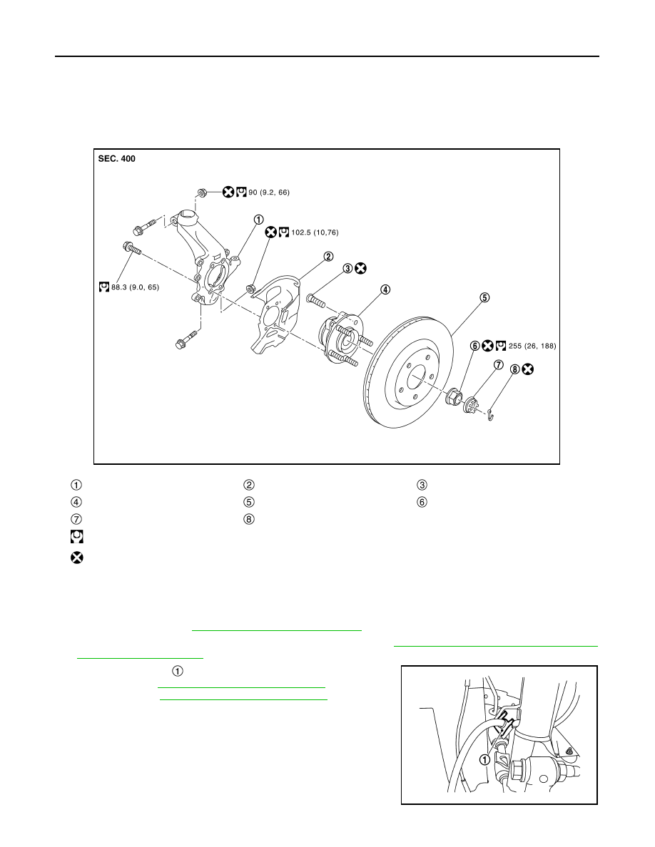
Exploded View
INFOID:0000000010824407
Removal and Installation
INFOID:0000000010824408
REMOVAL
1.
Remove tires. Refer to
WT-61, "Removal and Installation"
.
2.
Remove front wheel sensor from steering kunckle. Refer to
BRC-212, "FRONT WHEEL SENSOR :
.
3.
Remove lock plate
from strut assembly.
• LHD: Refer to
BR-24, "FRONT : Exploded View"
.
• RHD: Refer to
BR-88, "FRONT : Exploded View"
Steering knuckle
Splash guard
Hub bolt
Wheel hub and bearing assembly
Disc rotor
Wheel hub lock nut
Adjusting cap
Cotter pin
: N·m (kg-m, ft-lb)
: Always replace after every disassembly.
JMDIA1520GB
JSDIA3795ZZ