содержание .. 1260 1261 1262 1263 ..
Nissan X-Trail 32. Manual - part 1262
FAX-40
< REMOVAL AND INSTALLATION >
[2WD]
FRONT DRIVE SHAFT
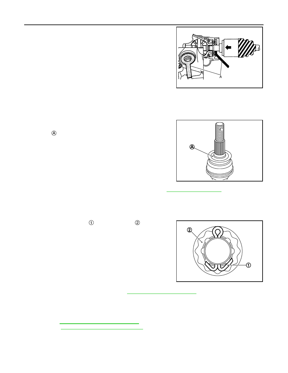
• Place the protector (A) (SST: KV38107900) onto transaxle assem-
bly to prevent damage to the differential side oil seal while inserting
drive shaft. Slide drive shaft sliding joint and tap with a hammer to
install securely.
CAUTION:
• Check that circular clip is completely engaged.
• Never reuse differential side oil seal.
• Clean the matching surface of wheel hub lock nut and wheel hub and bearing assembly.
CAUTION:
Never apply lubricating oil to these matching surface.
• Clean the matching surface of drive shaft and wheel hub and bear-
ing assembly. And then apply paste [service parts (440037S000)]
to surface
of joint sub-assembly of drive shaft.
CAUTION:
Apply paste to cover entire flat surface of joint sub-assembly
of drive shaft.
• Tighten the wheel hub lock nut to the specified torque. Refer to
CAUTION:
• Since the drive shaft is assembled by press-fitting, use the tightening torque range for the wheel
hub lock nut.
• Be sure to use torque wrench to tighten the wheel hub lock nut. Never use a power tool.
• Never reuse wheel hub lock nut.
• When installing a cotter pin
and adjusting cap
, securely bend
the basal portion to prevent rattles.
CAUTION:
Never reuse cotter pin.
• Perform inspection after installation. Refer to
.
Right Side
Note the following, and install in the reverse order of removal.
CAUTION:
Always replace differential side oil seal with new one when installing drive shaft.
• M/T: Refer to
TM-38, "Removal and Installation"
.
• CVT: Refer to
TM-429, "Removal and Installation"
.
JPDIF0023ZZ
Amount paste
: 1.0 – 3.0 g (0.04 – 0.10 oz)
JPDIG0122ZZ
JPDIF0295ZZ