Nissan X-Trail 32. Manual - part 1194


  Главная      Nissan     Nissan X-Trail 32 - Service Manual


поиск по сайту            


содержание   ..  1192  1193  1194  1195   ..


Nissan X-Trail 32. Manual - part 1194


SYSTEM

EXL-233

< SYSTEM DESCRIPTION >

[HALOGEN HEADLAMP]

C

D

E

F

G

H

I

J

K

M

A

B

EXL

N

O

P

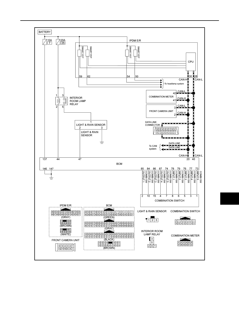
HIGH BEAM ASSIST SYSTEM : Circuit Diagram

INFOID:0000000011008682

HIGH BEAM ASSIST SYSTEM : Fail-safe

INFOID:0000000011008681

FRONT CAMERA UNIT TEMPORARY OPERATION CANCELLATION

• Temporary disabled status at high temperature
- If the vehicle is parked in direct sunlight under high temperature conditions, the system may be deactivated

automatically. And the system malfunction in information display.

JMLIA5513GB

EXL-234

< SYSTEM DESCRIPTION >

[HALOGEN HEADLAMP]

SYSTEM

- When interior temperature is reduced, the system will resume operation automatically.
• When vehicle front identification is difficult
- When vehicle front identification is difficult due to soiling of windshield glass and strong light shining from the

front, operation may be canceled temporarily. At this time, a warning is displayed on the vehicle information
display in the combination meter.

- Normal operation recovers when conditions improve.

DAYTIME RUNNING LIGHT SYSTEM

DAYTIME RUNNING LIGHT SYSTEM : System Description

INFOID:0000000010789789

SYSTEM DIAGRAM

OUTLINE

Daytime running light is controlled by daytime running light control function and combination switch reading
function of BCM, and smart FET control function of IPDM E/R.

DAYTIME RUNNING LIGHT OPERATION 

• BCM detects the combination switch condition by the combination switch reading function.
• BCM detects vehicle condition depending on the engine status signal and Stop/Start status signal* (received

from ECM via CAN communication).

• BCM transmits the daytime running light request signal to IPDM E/R via CAN communication according to

the daytime running light ON condition.

Daytime running light ON condition

- Engine running and any following conditions are satisfied.
• Lighting switch OFF
• Lighting switch AUTO (Only when the illumination judgment by auto light system is OFF. For details, refer to

EXL-228, "AUTO LIGHT SYSTEM : System Description"

.)

• IPDM E/R turns the integrated smart FET ON, and turns the daytime running light ON according to the day-

time running light request signal.

NOTE:
When the engine is stopped by the Stop/Start system, the operation of daytime running light system is not can-
celed.*
*: With Stop/Start system

JMLIA5230GB

SYSTEM

EXL-235

< SYSTEM DESCRIPTION >

[HALOGEN HEADLAMP]

C

D

E

F

G

H

I

J

K

M

A

B

EXL

N

O

P

DAYTIME RUNNING LIGHT SYSTEM : Circuit Diagram

INFOID:0000000010789790

DAYTIME RUNNING LIGHT SYSTEM : Fail-safe

INFOID:0000000010789791

FAIL-SAFE CONTROL BY DTC

IPDM E/R performs fail-safe control when any DTC are detected.

JMLIA5522GB

EXL-236

< SYSTEM DESCRIPTION >

[HALOGEN HEADLAMP]

SYSTEM

CAN COMMUNICATION CONTROL

When CAN communication with BCM is impossible, IPDM E/R performs fail-safe control. After CAN communi-
cation recovers normally, it also returns to normal control.

If No CAN Communication Is Available With BCM

HEADLAMP AIMING CONTROL (MANUAL)

HEADLAMP AIMING CONTROL (MANUAL) : System Description

INFOID:0000000010789792

The headlamp levelizer adjusts the headlamp light axis upward and downward with the aiming motor inte-
grated in the front combination lamp.

TURN SIGNAL AND HAZARD WARNING LAMP SYSTEM

TURN SIGNAL AND HAZARD WARNING LAMP SYSTEM : System Description

INFOID:0000000010789793

SYSTEM DIAGRAM

OUTLINE

Turn signal lamp and hazard warning lamp is controlled by combination switch reading function and the flasher
control function of BCM.

TURN SIGNAL LAMP OPERATION

• BCM detects the combination switch condition by the combination switch reading function.
• BCM supplies voltage to the right (left) turn signal lamp circuit when the ignition switch is ON and the turn

signal switch is in the right (left) position. BCM blinks the turn signal lamp.

HAZARD WARNING LAMP OPERATION

BCM supplies voltage to both turn signal lamp circuits when the hazard switch is ON. BCM blinks the hazard
warning lamp.

TURN SIGNAL INDICATOR LAMP AND TURN SIGNAL SOUND OPERATION

DTC

CONSULT display description

Fail-safe

B1231

DTRL RH PWR SPLY CIRC

[CIRC 
SHORT TO 
GRND]

Shuts off the power supply to the daytime running light RH 
power supply circuit until the daytime running light ON 
conditions are no longer satisfied.

B20CB

DTRL LH PWR SPLY CIRC

[CIRC 
SHORT TO 
GRND]

Shuts off the power supply to the daytime running light LH 
power supply circuit until the daytime running light ON 
conditions are no longer satisfied.

Control part

Fail-safe operation

Daytime running light

Daytime running light: OFF

JMLIA5232GB


содержание   ..  1192  1193  1194  1195   ..