Nissan X-Trail 32. Manual - part 1192


  Главная      Nissan     Nissan X-Trail 32 - Service Manual


поиск по сайту            


содержание   ..  1190  1191  1192  1193   ..


Nissan X-Trail 32. Manual - part 1192


SYSTEM

EXL-225

< SYSTEM DESCRIPTION >

[HALOGEN HEADLAMP]

C

D

E

F

G

H

I

J

K

M

A

B

EXL

N

O

P

SYSTEM

HEADLAMP SYSTEM

HEADLAMP SYSTEM : System Description

INFOID:0000000010789784
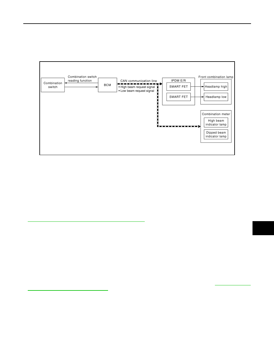
SYSTEM DIAGRAM

OUTLINE

Headlamp is controlled by combination switch reading function and headlamp control function of BCM, and
smart FET control function of IPDM E/R.

HEADLAMP (LO) OPERATION 

• BCM detects the combination switch condition with the combination switch reading function.
• BCM transmits the low beam request signal to IPDM E/R and the combination meter with CAN communica-

tion according to the headlamp (LO) ON condition.

Headlamp (LO) ON condition (When any of the following conditions are satisfied)

- Lighting switch 2ND
- Lighting switch AUTO (Only when the illumination judgment by auto light system is ON. For details, refer to

EXL-228, "AUTO LIGHT SYSTEM : System Description"

.)

- Lighting switch PASS
• IPDM E/R turns the integrated smart FET ON according to low beam request signal and supplies power sup-

ply to headlamp (LO).

• Combination meter turns the dipped beam indicator lamp ON according to the low beam request signal.

HEADLAMP (HI) OPERATION

• BCM transmits the high beam request signal to IPDM E/R and the combination meter with CAN communica-

tion according to the headlamp (HI) ON condition. 

Headlamp (HI) ON condition (When any of the following conditions are satisfied)

- Lighting switch HI with the lighting switch 2ND
- Lighting switch HI with the lighting switch AUTO (Only when the illumination judgment by auto light system is

ON and the illumination judgment by high beam assist system is ON. For details, refer to 

EXL-228, "AUTO

LIGHT SYSTEM : System Description"

.)

- Lighting switch PASS
• IPDM E/R turns the integrated headlamp high smart FET ON according to high beam request signal and

supplies power supply to headlamp (HI).

• Combination meter turns the high beam indicator lamp ON according to the high beam request signal. 

FOLLOW ME HOME FUNCTION

When the driver is moving to the house entrance from the own vehicle, headlamp is kept still ON by the follow
me home function of BCM.

JMLIA5241GB

EXL-226

< SYSTEM DESCRIPTION >

[HALOGEN HEADLAMP]

SYSTEM

• When BCM detects the input of lighting switch PASS while all of the following conditions are satisfied, it

transmits the low beam request signal for a period of time to IPDM E/R and the combination meter through
CAN communication.

Follow me home ON condition (When all of the following conditions are satisfied)

- Ignition switch OFF
- Lighting switch OFF or AUTO
• IPDM E/R turns the integrated smart FET ON according to low beam request signal and supplies power sup-

ply to headlamp (LO).

• Combination meter turns the dipped beam indicator lamp ON according to the low beam request signal.
• When in any of following conditions, follow me home function can be cancelled while follow me home func-

tion is operating.

Follow me home OFF condition (When any of the following conditions are satisfied)

- Ignition switch other than OFF
- Lighting switch other than OFF or AUTO
- Follow me home operating time is expired
NOTE:
• Flash-to-pass operation illumination time for 1 time can be extended to approximately 30 seconds during

operation of follow me home function.

• Flash-to-pass operation can be illuminated continuously for approximately 60 seconds (flash-to-pass opera-

tion, 2 times), approximately 90 seconds (flash-to-pass operation, 3 times), and a maximum of approxi-
mately 120 seconds (flash-to-pass operation, 4 times).

SYSTEM

EXL-227

< SYSTEM DESCRIPTION >

[HALOGEN HEADLAMP]

C

D

E

F

G

H

I

J

K

M

A

B

EXL

N

O

P

HEADLAMP SYSTEM : Circuit Diagram

INFOID:0000000010789785

HEADLAMP SYSTEM : Fail-safe

INFOID:0000000010789786

FAIL-SAFE CONTROL BY DTC

IPDM E/R performs fail-safe control when any DTC are detected.

JMLIA5379GB

EXL-228

< SYSTEM DESCRIPTION >

[HALOGEN HEADLAMP]

SYSTEM

CAN COMMUNICATION CONTROL

When CAN communication with BCM is impossible, IPDM E/R performs fail-safe control. After CAN communi-
cation recovers normally, it also returns to normal control.

If No CAN Communication Is Available With BCM

AUTO LIGHT SYSTEM

AUTO LIGHT SYSTEM : System Description

INFOID:0000000010789787

SYSTEM DIAGRAM

OUTLINE

•  Auto light system is controlled by each function of BCM and IPDM E/R.

Control by BCM

- Combination switch reading function
- Auto light function
- Fog override function

Control by IPDM E/R

- Smart FET control function
• Auto light system has the auto light function and fog override function.
- Auto light function automatically turns ON/OFF the exterior lamps*, depending on the outside brightness.

DTC

CONSULT display description

Fail-safe

B20CE

HL (HI) LH PWR SPLY CIRC

[CIRC 
SHORT TO 
GRND]

Shuts off the power supply to the headlamp (HI) LH power 
supply circuit until the headlamp (HI) ON conditions are 
no longer satisfied.

B20CF

HL (HI) RH PWR SPLY CIRC

[CIRC 
SHORT TO 
GRND]

Shuts off the power supply to the headlamp (HI) RH pow-
er supply circuit until the headlamp (HI) ON conditions are 
no longer satisfied.

B20D0

HL (LO) LH PWR SPLY CIRC

[CIRC 
SHORT TO 
GRND]

Shuts off the power supply to the headlamp (LO) LH pow-
er supply circuit until the headlamp (LO) ON conditions 
are no longer satisfied.

B20D1

HL (LO) RH PWR SPLY CIRC

[CIRC 
SHORT TO 
GRND]

Shuts off the power supply to the headlamp (LO) RH pow-
er supply circuit until the headlamp (LO) ON conditions 
are no longer satisfied.

Control part

Fail-safe operation

Headlamp

• Turns ON the headlamp (LO) when the ignition switch is turned ON.
• Turns OFF the headlamp (LO) when the ignition switch is turned OFF.
• Headlamp (HI): OFF

JMLIA5228GB


содержание   ..  1190  1191  1192  1193   ..