Nissan X-Trail 32. Manual - part 1179


  Главная      Nissan     Nissan X-Trail 32 - Service Manual


поиск по сайту            


содержание   ..  1177  1178  1179  1180   ..


Nissan X-Trail 32. Manual - part 1179


LIGHT & RAIN SENSOR

EXL-173

< DTC/CIRCUIT DIAGNOSIS >

[LED HEADLAMP]

C

D

E

F

G

H

I

J

K

M

A

B

EXL

N

O

P

Is the inspection result normal?

YES

>> GO TO 4.

NO

>> Repair or replace harness.

4.

CHECK LIGHT & RAIN SENSOR SIGNAL

1.

Connect light & rain sensor connector.

2.

Turn ignition switch ON.

3.

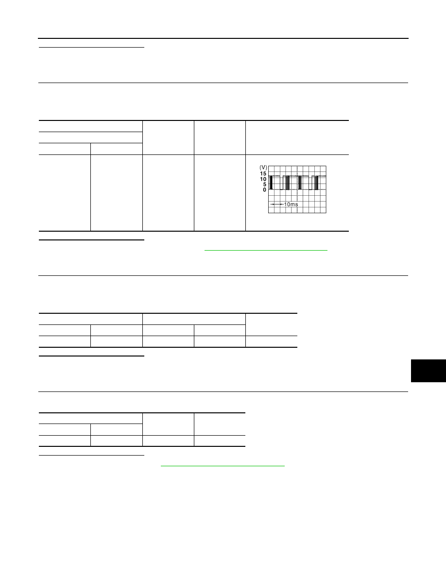
Check voltage between BCM harness connector and ground.

Is the inspection result normal?

YES

>> Replace light & rain sensor. Refer to 

EXL-195, "Removal and Installation"

.

NO

>> GO TO 5.

5.

CHECK LIGHT & RAIN SENSOR SIGNAL CIRCUIT (OPEN)

1.

Turn ignition switch OFF.

2.

Disconnect BCM connector and light & rain sensor connector.

3.

Check continuity between BCM harness connector and light & rain sensor harness connector.

Is the inspection result normal?

YES

>> GO TO 6.

NO

>> Repair or replace harness.

6.

CHECK LIGHT & RAIN SENSOR SIGNAL CIRCUIT (SHORT)

Check continuity between BCM harness connector and ground.

Is the inspection result normal?

YES

>> Replace BCM. Refer to 

BCS-121, "Removal and Installation"

.

NO

>> Repair or replace harness.

+

-

Condition

Voltage

(Approx.)

BCM

Connector

Terminal

M87

47

Ground 

Ignition switch 
ON

8.7V

JPMIA0156GB

BCM

Light & rain sensor

Continuity

Connector

Terminal

Connector

Terminal

M87

47

R20

2

Existed

BCM

Continuity

Connector

Terminal

M87

47

Ground

Not existed

EXL-174

< DTC/CIRCUIT DIAGNOSIS >

[LED HEADLAMP]

HAZARD SWITCH

HAZARD SWITCH

Component Function Check

INFOID:0000000010788863

1.

CHECK HAZARD SWITCH SIGNAL

With CONSULT

1.

Turn ignition switch ON.

2.

Select “FLASHER” of “BCM” using CONSULT.

3.

Select “HAZARD SW” in “Data Monitor” mode.

4.

With operating the hazard switch, check the monitor status.

Is the inspection result normal?

YES

>> Hazard switch circuit is normal.

NO

>> Refer to 

EXL-174, "Diagnosis Procedure"

.

Diagnosis Procedure

INFOID:0000000010788864

1.

CHECK HAZARD SWITCH SIGNAL

1.

Turn ignition switch OFF.

2.

Disconnect hazard switch connector.

3.

Check voltage between hazard switch connector and ground.

Is the inspection result normal?

YES

>> GO TO 4.

NO

>> GO TO 2.

2.

CHECK HAZARD SWITCH SIGNAL CIRCUIT (OPEN)

1.

Disconnect BCM connector.

2.

Check continuity between hazard switch harness connector and BCM harness connector.

Is the inspection result normal?

YES

>> GO TO 3.

NO

>> Repair or replace harness.

3.

CHECK HAZARD SWITCH SIGNAL CIRCUIT (SHORT)

Check continuity between hazard switch harness connector and ground.

Is the inspection result normal?

YES

>> Replace BCM. Refer to 

BCS-121, "Removal and Installation"

.

Monitor item

Condition

Monitor status

HAZARD SW

Hazard switch

ON

On

OFF

Off

+

-

Voltage

Hazard switch

Connector

Terminal

M45

2

Ground

9 – 16 V

Hazard switch

BCM

Continuity

Connector

Terminal

Connector

Terminal

M45

2

M87

51

Existed

Hazard switch

Continuity

Connector

Terminal

M45

2

Ground

Not existed

HAZARD SWITCH

EXL-175

< DTC/CIRCUIT DIAGNOSIS >

[LED HEADLAMP]

C

D

E

F

G

H

I

J

K

M

A

B

EXL

N

O

P

NO

>> Repair or replace harness.

4.

CHECK HAZARD SWITCH GROUND CIRCUIT

Check continuity between hazard switch harness connector and ground.

Is the inspection result normal?

YES

>> GO TO 5.

NO

>> Repair or replace harness.

5.

CHECK HAZARD SWITCH

Check hazard switch. Refer to 

EXL-175, "Component Inspection"

.

Is the inspection result normal?

YES

>> INSPECTION END

NO

>> Replace hazard switch. Refer to 

EXL-197, "Removal and Installation"

.

Component Inspection

INFOID:0000000010788865

1.

CHECK HAZARD SWITCH

1.

Turn ignition switch OFF.

2.

Disconnect hazard switch connector.

3.

Check continuity of hazard switch terminals.

Is the inspection result normal?

YES

>> INSPECTION END

NO

>> Replace hazard switch. Refer to 

EXL-197, "Removal and Installation"

.

Hazard switch

Continuity

Connector

Terminal

M45

1

Ground

Existed

Hazard switch

Condition

Continuity

Terminal

2

1

Hazard switch

ON

Existed

OFF

Not existed

EXL-176

< SYMPTOM DIAGNOSIS >

[LED HEADLAMP]

EXTERIOR LIGHTING SYSTEM SYMPTOMS

SYMPTOM DIAGNOSIS

EXTERIOR LIGHTING SYSTEM SYMPTOMS

Symptom Table

INFOID:0000000010788866

NOTE:
Perform the self-diagnosis with CONSULT before the symptom diagnosis. Perform the trouble diagnosis if any
DTC is detected.

Symptom

Possible cause

Inspection item

Headlamp (HI) is not turned 
ON

One side

• Headlamp (HI) power supply cir-

cuit

• Front combination lamp internal 

circuit

- LED [Headlamp (HI)]
- LED headlamp control module
- Harness
• IPDM E/R

Headlamp (HI) circuit
Refer to 

EXL-146, "Component Func-

tion Check"

.

Both sides

Symptom diagnosis
 “BOTH SIDE HEADLAMPS (HI) ARE NOT TURNED ON”
Refer to 

EXL-180, "Diagnosis Procedure"

.

High beam indicator lamp is not turned ON
[Headlamp (HI) is turned ON]

Combination meter

Combination meter
Data monitor “HI-BEAM IND”

Headlamp (LO) is not 
turned ON

One side

• Headlamp (LO) power supply cir-

cuit

• Front combination lamp internal 

circuit

- LED [Headlamp (LO)]
- LED headlamp control module
- Harness
• IPDM E/R

Headlamp (LO) circuit
Refer to 

EXL-147, "Component Func-

tion Check"

.

Both sides

Symptom diagnosis
 “BOTH SIDE HEADLAMPS (LO) ARE NOT TURNED ON”
Refer to 

EXL-181, "Diagnosis Procedure"

.

Dipped beam indicator lamp is not turned ON
[Headlamp (LO) is turned ON]

Combination meter

Combination meter
Data monitor “DIPPED BEAM IND”

Headlamp (HI) and (LO) is not turned ON

• LED headlamp ground circuit
• Front combination lamp internal 

circuit

- LED headlamp control module
- Harness

LED headlamp
Refer to 

EXL-148, "Diagnosis Proce-

dure"

.

Each lamp is not turned ON/OFF with lighting switch 
AUTO

• Combination switch input/output 

signal circuit

• Combination switch
• BCM

Combination switch
Refer to 

BCS-119, "Symptom Table"

.

• Light & rain sensor power supply/

ground/signal circuit

• Light & rain sensor
• BCM

Light & rain sensor
Refer to 

EXL-172, "Component Func-

tion Check"

.

Parking lamp is not turned ON

• Parking lamp power supply/

ground circuit

• Front combination lamp internal 

circuit

- LED  (Parking  lamp)
- Control circuit
- Harness
• IPDM E/R

Parking lamp circuit
Refer to 

EXL-151, "Component Func-

tion Check"

.


содержание   ..  1177  1178  1179  1180   ..