содержание .. 1172 1173 1174 1175 ..
Nissan X-Trail 32. Manual - part 1174
TAIL LAMP CIRCUIT
EXL-153
< DTC/CIRCUIT DIAGNOSIS >
[LED HEADLAMP]
C
D
E
F
G
H
I
J
K
M
A
B
EXL
N
O
P
TAIL LAMP CIRCUIT
Component Function Check
INFOID:0000000010788846
1.
CHECK TAIL LAMP OPERATION
With CONSULT
1.
Select “TAIL LAMP” in “Active Test” mode of “IPDM E/R” using CONSULT.
2.
With operating the test items, check that the tail lamp is turned ON.
Is the inspection result normal?
YES
>> Tail lamp circuit is normal.
NO
>> Refer to
EXL-153, "Diagnosis Procedure"
.
Diagnosis Procedure
INFOID:0000000010788847
1.
CHECK TAIL LAMP OUTPUT VOLTAGE
With CONSULT
1.
Turn ignition switch OFF.
2.
Disconnect the following connectors.
-
Rear combination lamp LH (body side)
-
Rear combination lamp RH (body side)
-
Rear combination lamp LH (back door side)
-
Rear combination lamp RH (back door side)
3.
Turn ignition switch ON.
4.
Select “TAIL LAMP” in “Active Test” mode of “IPDM E/R” using CONSULT.
5.
With operating the test items, check voltage between IPDM E/R harness connector and ground.
Is the inspection result normal?
YES
>> GO TO 2.
NO
>> Replace IPDM E/R. Refer to
PCS-60, "Removal and Installation"
.
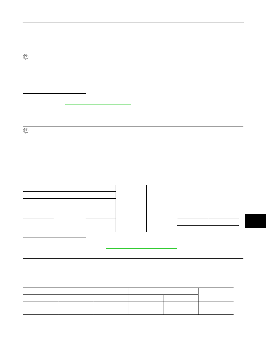
2.
CHECK TAIL LAMP POWER SUPPLY CIRCUIT
1.
Turn ignition switch OFF.
2.
Disconnect IPDM E/R connector.
3.
Check continuity between IPDM E/R harness connector and each rear combination lamp harness con-
nector.
Body side
On
: Tail Lamp ON
Off
: Tail lamp OFF
+
-
Test item
Voltage
IPDM E/R
Connector
Terminal
RH
E10
17
Ground
TAIL LAMP
On
9 – 16 V
Off
0 – 1 V
LH
4
On
9 – 16 V
Off
0 – 1 V
IPDM E/R
Rear combination lamp (body side)
Continuity
Connector
Terminal
Connector
Terminal
RH
E10
17
B59
1
Existed
LH
4
B80